EasyManua.ls Logo

Nortek Signature Series User Manual

Nortek Signature Series
85 pages
To Next Page IconTo Next Page
To Previous Page IconTo Previous Page
Page #7 background imageLoading...
Page #7 background image
Basic interface concept 7
© 2017 Nortek AS
timeout value in Confirmation and Data Retrieval modes is 60 seconds. There is also a timeout in
Command Mode when operating over the serial interface. If no commands are received for 5
minutes, a break or a sequence of @@@@@@ must be sent to wake up the processor.
2.2 Break
<BREAK> over the serial RS232/RS422 interface is defined as:
@@@@@@ <delay 100 milliseconds> K1W%!Q <delay 300 milliseconds> K1W%!Q
The @@@@@@ are used to wake up the processor when it is in sleep mode since the instrument
will only be able to monitor activity on the serial line when it sleeps. The second sequence of the
actual break characters is there to ensure that a break is detected even when the instrument is
waking up due to some other cause (e.g. alarm from the real time clock). This ensures that the
processor will interpret the following command correctly.
The figure and the table below show the specified timing of the BREAK sequence:
K1W%!Q
K1W%!Q
@@@@@@
t1
t2
t3
Figure: Break timing
Symbol
Parameter
Min.
Typical
Max.
t1
Time from end of @-sequence to start of first K1W%!Q-
sequence.
100
150
t2
Time from end of @-sequence to start of second K1W%!
Q-sequence.
500
1000
2000
t3
Time between first and second K1W%!Q-sequence.
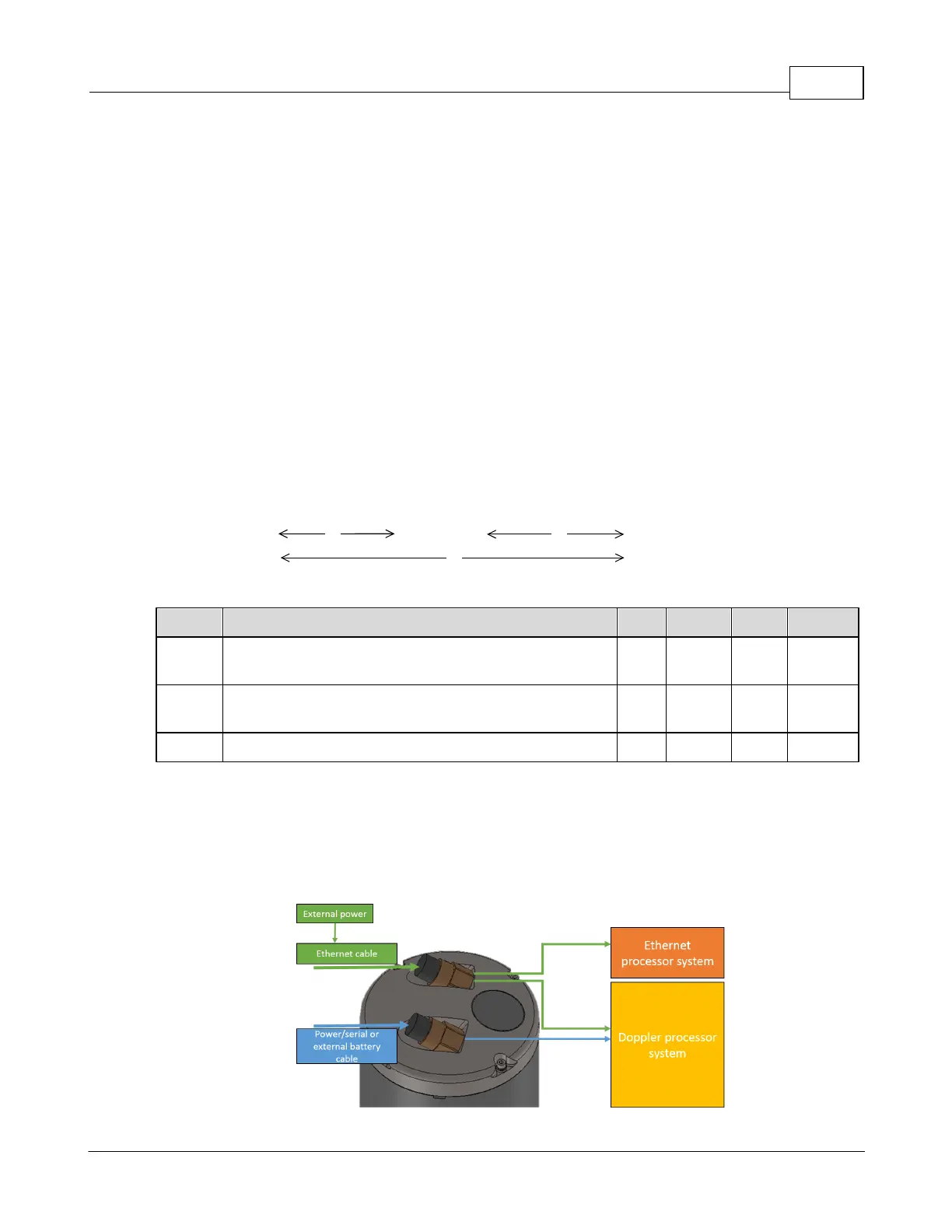
300
400
2.3 Dual Processor
The AD2CP uses a two-processor (DSP) design; one dedicated to Doppler processing (BBP) and the
other to Interface (SEC). The primary interface is Ethernet, so the Interface processor is only powered
when external power is applied. Note that powering through the Ethernet cable will also power the rest of
the electronics.
Figure: Power distribution relating to the two-processor design.

Table of Contents

Question and Answer IconNeed help?

Do you have a question about the Nortek Signature Series and is the answer not in the manual?

Nortek Signature Series Specifications

General IconGeneral
TypeAcoustic Doppler Current Profiler (ADCP)
Operating Temperature-5°C to +45°C
Storage Temperature-20°C to +60°C
Temperature SensorIntegrated
Pressure SensorIntegrated
Compass and Tilt SensorIntegrated
Data StorageInternal memory
Communication InterfacesEthernet, RS-232
Depth RatingUp to 6000 meters (depending on model)
Data OutputASCII, binary
Beam AngleVaries by model
Velocity Accuracy±0.5% of measured velocity ±1 mm/s

Summary

Introduction

Basic Interface Concept

Instrument Modes of Operation

Explains the different operational modes of the profiler and how to transition between them.

Break Sequence Timing

Details the timing parameters for the break sequence used for interface communication.

Dual Processor Architecture

Describes the AD2CP's two-processor design for Doppler processing and interface management.

Instrument Interfaces

Command Interface

Details the ASCII-based command interface via terminal software or Telnet.

Telemetry Data Transfer

Explains telemetry as a subset transfer system for low-bandwidth links.

Ethernet Communication

Explains TCP/IP communication protocols and ports used by the instrument.

User Cases and Examples

Average Velocity Data and NMEA

Example of configuring and downloading averaged velocity data using NMEA format.

Download Telemetry File via FTP

Demonstrates setting up and downloading a telemetry file using the FTP protocol.

Download Telemetry File via Serial Port

Procedure for downloading telemetry data in chunks over a serial connection.

Erase Telemetry File

Steps to erase the telemetry file from the instrument's storage.

Check Instrument State over Ethernet

Method for verifying the instrument's current operational status via Ethernet.

Instrument Commands

List of Commands

A comprehensive, categorized list of available commands with their functions.

Instrument Settings Commands

Commands for configuring instrument settings like clock, instance, and user parameters.

Measurement Plan Commands

Commands used to define measurement plans, intervals, and types.

Data Retrieval Commands

Commands for downloading files and inquiring instrument state.

Telemetry Configuration Commands

Commands for setting up telemetry data formats and parameters.

Data Formats

Data Packet Header Definition

Details the structure and fields of the data packet header.

Burst/Average Data Record Definition

Defines the format for Burst and Average data records (DF3).

Bottom Track Data Record Definition

Defines the format for Bottom Track data records (DF20).

String Data Record Definition

Describes the String Data Record used for storing configuration and text data.

Data Limit Formats

Explains the format for returning valid argument values and ranges.

Telemetry Data Formats

Averaging Mode Telemetry Formats

Describes available telemetry data formats for the Averaging mode.

AWAC NMEA Format (DF=100)

Details the AWAC NMEA format, including configuration and sensor data sentences.

NMEA Format 1 and 2 (DF=101/102)

Explains NMEA formats 1 and 2 for configuration and sensor data.

NMEA Format 3 and 4 (DF=103/104)

Details NMEA formats 3 and 4 for header, sensor, and averaged data.

Burst Mode NMEA Formats

Describes NMEA formats 1 and 2 for Burst mode configuration and sensor data.

Altimeter Telemetry Formats

Lists available NMEA data formats for Altimeter telemetry.

DVL Bottom Track Telemetry Formats

Lists available NMEA data formats for DVL Bottom Track telemetry.

ASCII Data Input via Ethernet

Provides sample code for receiving ASCII data over Ethernet.

Related product manuals