6-2
Ordering information
AN2016 Cabinet User Guide Rel 1.0 Standard May 1999
For a front view of frame/bay A, B, C, D, E and F, the equipment frame/bay
layouts and mounting positions, see Figure 6-1, Figure 6-2, Figure 6-3,
Figure 6-4, Figure 6-5 and Figure 6-6.
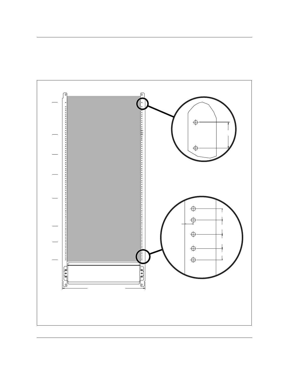
Figure 6-1
672-line configuration (front view frame/bay A)
AN0089.eps
Reserved and dedicated
positions for future
expansion
(Note)
Front view
79
64
54
44
32
18
10
01
24.335 reference
1.250
.500
.625
.625
.375
.500
Note:
The following empty spaces are reserved and dedicated only for
future expansion using CDS shelves or future UE 9000 shelves.