Wiring a Signaling Line Circuit (SLC)
,QVWDOODWLRQ
AFP-300/AFP-400 Installation PN 50253:C1 05/22/97 2-51
:LULQJ DQ 1)3$ 6W\OH %
,'& ZLWK 00;V
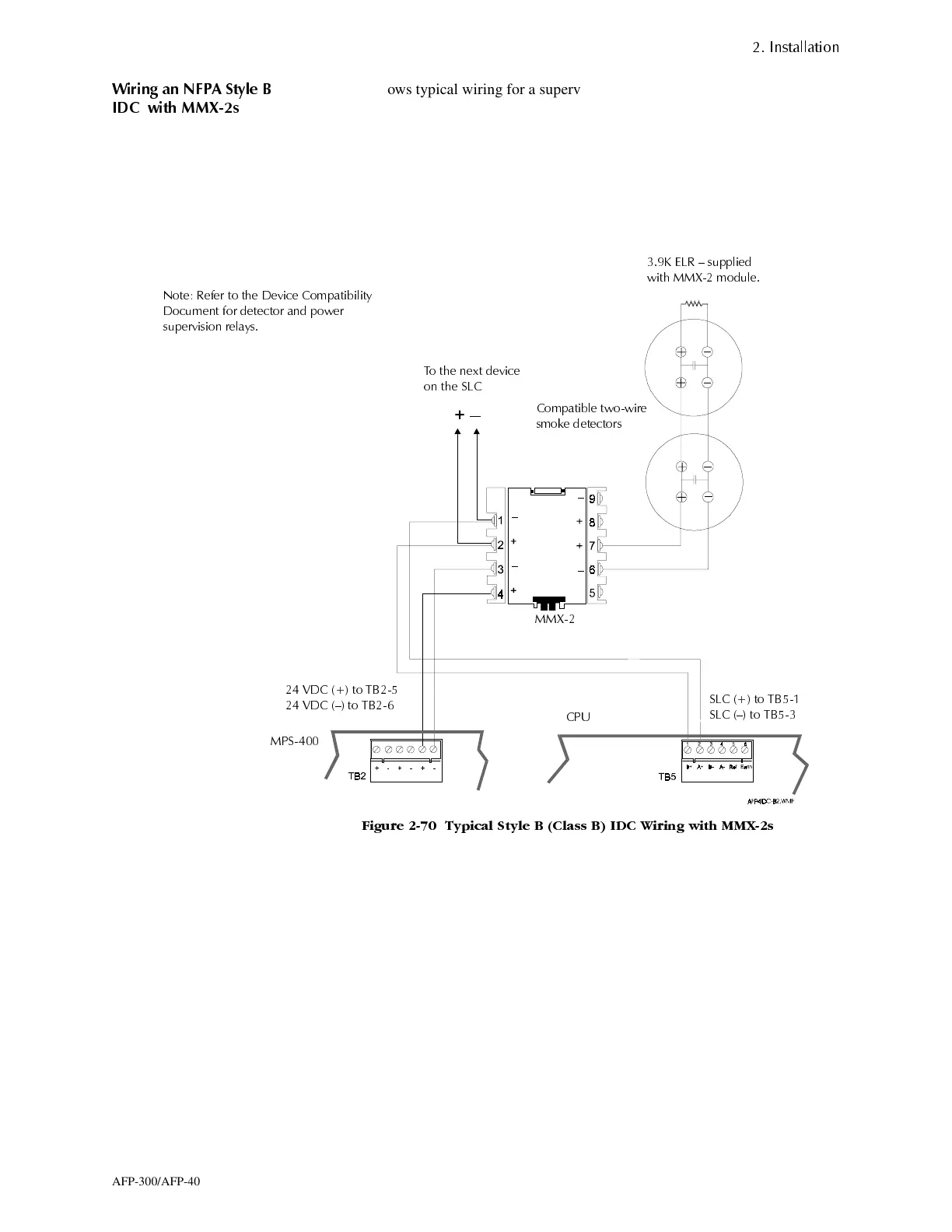
Figure 2-70 shows typical wiring for a supervised and power-limited NFPA Style B
IDC using MMX-2 modules. For more information, refer to the MMX-2 Installation
Instructions, Document M500-03-00.
Wiring guidelines for this IDC are:
• Maximum Initiating Device Circuit (IDC) resistance is 25 ohms.
• Maximum alarm current is 90 mA.
• Maximum detector standby current is 2.4 mA.
)LJXUH 7\SLFDO 6W\OH % &ODVV % ,'& :LULQJ ZLWK 00;V
. (/5 ² VXSSOLHG
ZLWK 00; PRGXOH
7R WKH QH[W GHYLFH
RQ WKH 6/&
&RPSDWLEOH WZRZLUH
VPRNH GHWHFWRUV
&38
036
00;
9'& WR 7%
9'& ² WR 7%
6/& WR 7%
6/& ² WR 7%
1RWH 5HIHU WR WKH 'HYLFH &RPSDWLELOLW\
'RFXPHQW IRU GHWHFWRU DQG SRZHU
VXSHUYLVLRQ UHOD\V
www.PDF-Zoo.com
 Loading...


