,QVWDOODWLRQ
Wiring a Signaling Line Circuit (SLC)
2-56 AFP-300/AFP-400 Installation PN 50253:C1 05/22/97
6W\OH < 1$& &LUFXLWV
7ZR:LUH
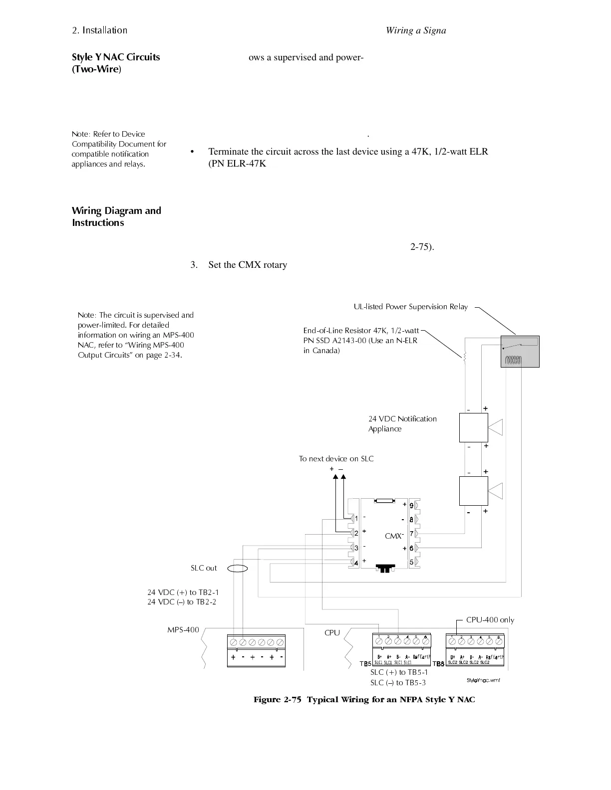
Figure 2-75 shows a supervised and power-limited NFPA Style Y NAC using a CMX
module. This shows polarized alarm notification appliances connected to CMX
modules in a two-wire configuration. A CMX module can control 2 A of resistive load
(on electronic devices) or 1 A of inductive load (on mechanical bells and horns). If
installing more than one CMX NAC, install the power supervision relay on the 24 VDC
power bus after the last CMX.
1RWH 5HIHU WR 'HYLFH
&RPSDWLELOLW\ 'RFXPHQW IRU
FRPSDWLEOH QRWLILFDWLRQ
DSSOLDQFHV DQG UHOD\V
• Do not T-tap or branch a Style Y circuit.
• Terminate the circuit across the last device using a 47K, 1/2-watt ELR
(PN ELR-47K).
• Do not run wiring under any terminals. To maintain supervision, break the wire
run.
:LULQJ 'LDJUDP DQG
,QVWUXFWLRQV
Connect the NAC as follows:
1. Connect the SLC to CMX terminals 1 (–) and 2 (+).
2. Connect 24 VDC power to MPS-400 TB2 (Figure 2-75).
3. Set the CMX rotary switches to the required SLC address. (The CMX takes one
module address on the SLC.) For instructions on setting rotary switches, see
Figure 2-68 on page 2-49.
)LJXUH 7\SLFDO :LULQJ IRU DQ 1)3$ 6W\OH < 1$&
1RWH 7KH FLUFXLW LV VXSHUYLVHG DQG
SRZHUOLPLWHG )RU GHWDLOHG
LQIRUPDWLRQ RQ ZLULQJ DQ 036
1$& UHIHU WR ´:LULQJ 036
2XWSXW &LUFXLWVµ RQ SDJH
8/OLVWHG 3RZHU 6XSHUYLVLRQ 5HOD\
(QGRI/LQH 5HVLVWRU . ZDWW
31 66' $ 8VH DQ 1(/5
LQ &DQDGD
9'& 1RWLILFDWLRQ
$SSOLDQFH
7R QH[W GHYLFH RQ 6/&
²
6/& WR 7%
6/& ² WR 7%
9'& WR 7%
9'& ² WR 7%
&0;
6/& RXW
&38
036
&38 RQO\
www.PDF-Zoo.com
 Loading...


