Wiring a Signaling Line Circuit (SLC)
,QVWDOODWLRQ
AFP-300/AFP-400 Installation PN 50253:C1 05/22/97 2-49
:LULQJDQ,'&ZLWK00;0RGXOHV
2YHUYLHZ RI 0RQLWRU
0RGXOHV 00; 6HULHV
The MMX Monitor Module is an addressable module that monitors conventional
contact-type, alarm, supervisory, security, alert, or trouble initiating devices. You can
wire a supervised MMX circuit as an NFPA Style B or Style D IDC.
• NFPA Style B Initiating Device Circuit – see Figure 2-69 and Figure 2-70.
• NFPA Style D Initiating Device Circuit – see Figure 2-71 and Figure 2-72.
• There are three models of MMX Series monitor modules as follows:
MMX-1
– Use MMX-1 modules for wiring Style B and Style D IDCs.
MMX-2
– The MMX-2 Monitor Module is an addressable module used to monitor
a single Initiating Device Circuit of smoke detectors. Use MMX-2 modules to
monitor conventional, two-wire smoke detectors. The MMX-2 requires an
additional connection of 24 VDC filtered, low-noise and resettable power on
MMX-2 Terminals 3 (–) and 4 (+).
MMX-101
(Style B circuits only) – The MMX-101 is a miniature addressable
module that is functionally and electrically identical to an MMX-1 Monitor
Module. Because of the smaller size, an MMX-101 is ideally suited for mounting
directly in the electrical box of a monitored contact-type device.
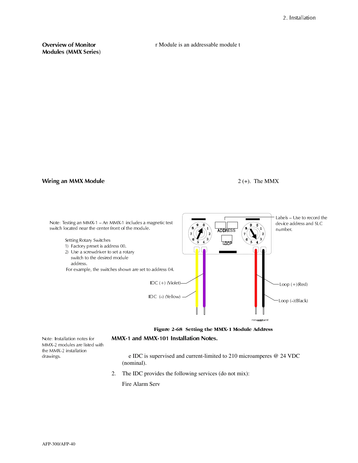
:LULQJ DQ 00; 0RGXOH
Connect the SLC wiring to MMX terminals 1 (–) and 2 (+). The MMX takes one
module address on the SLC. Use the rotary switches on the MMX to set the module to
the required SLC address. (For example, the MMX-1 shown in Figure 2-68 is set to
SLC address 04.)
)LJXUH 6HWWLQJ WKH 00; 0RGXOH $GGUHVV
1RWH ,QVWDOODWLRQ QRWHV IRU
00; PRGXOHV DUH OLVWHG ZLWK
WKH 00; LQVWDOODWLRQ
GUDZLQJV
00; DQG 00; ,QVWDOODWLRQ 1RWHV
When installing MMX-1 and MMX-101
modules, note the following:
1. The IDC is supervised and current-limited to 210 microamperes @ 24 VDC
(nominal).
2. The IDC provides the following services (do not mix):
Fire Alarm Service.
Automatic/Manual Waterflow Alarm Service with normally open contact devices.
Sprinkler Supervision with normally open contact devices.
Security Service.
3. Maximum IDC wiring resistance is 20 ohms.
6HWWLQJ 5RWDU\ 6ZLWFKHV
)DFWRU\ SUHVHW LV DGGUHVV
8VH D VFUHZGULYHU WR VHW D URWDU\
VZLWFK WR WKH GHVLUHG PRGXOH
DGGUHVV
)RU H[DPSOH WKH VZLWFKHV VKRZQ DUH VHW WR DGGUHVV
1RWH 7HVWLQJ DQ 00; ² $Q 00; LQFOXGHV D PDJQHWLF WHVW
VZLWFK ORFDWHG QHDU WKH FHQWHU IURQW RI WKH PRGXOH
,'& ² <HOORZ
,'& 9LROHW
/RRS 5HG
/RRS ²%ODFN
/DEHOV ² 8VH WR UHFRUG WKH
GHYLFH DGGUHVV DQG 6/&
QXPEHU
www.PDF-Zoo.com
 Loading...


