Wiring a Signaling Line Circuit (SLC)
,QVWDOODWLRQ
AFP-300/AFP-400 Installation PN 50253:C1 05/22/97 2-61
6/&:LULQJZLWKD%;/$GGUHVVDEOH0DQXDO3XOO6WDWLRQ
%*;/ 2YHUYLHZ
The BGX-101L is an addressable manual pull station with a key-lock reset feature.
1. Connect the SLC to terminal screws (+) and (–).
2. Connect the BGX-101L to the CPU as listed in Table 2-24:
Table 2-24 BGX-101 SLC Connections
3. Set the SLC address of the BGX-101L as shown in Figure 2-80.
%*;/ :LULQJ
&RQQHFWLRQV
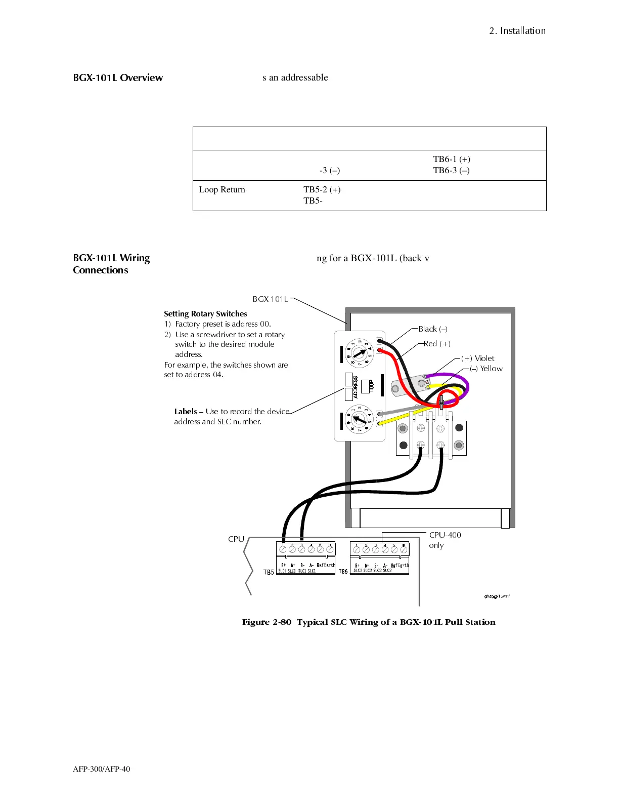
Figure 2-80 shows typical wiring for a BGX-101L (back view shown) and provides
instructions for setting the SLC address:
)LJXUH 7\SLFDO 6/& :LULQJ RI D %*;/ 3XOO 6WDWLRQ
Connection SLC 1 SLC 2 (CPU-400 only)
Loop Out TB5-1 (+)
TB5-3 (–)
TB6-1 (+)
TB6-3 (–)
Loop Return TB5-2 (+)
TB5-4 (–)
TB6-2 (+)
TB6-4 (–)
6HWWLQJ 5RWDU\ 6ZLWFKHV
)DFWR U\ SUHVHW LV DGGUHVV
8VH D VFUHZGULYHU WR VHW D URWDU\
VZLWFK WR WKH GHVLUHG PRGXOH
DGGUHVV
)RU H[DPSOH WK H VZLWFKHV VKRZQ DUH
VHW WR DGGUHVV
/DEHOV
² 8VH WR UHFRUG WKH GHYLFH
DGGUHVV DQG 6/& QXPEHU
%*;/
%ODFN ²
5HG
² <HOORZ
&38
&38
RQO\
9LROHW
www.PDF-Zoo.com
 Loading...


