,QVWDOODWLRQ
Wiring a Signaling Line Circuit (SLC)
2-60 AFP-300/AFP-400 Installation PN 50253:C1 05/22/97
6/&: LULQJZLWKDQ,QWHOOLJHQW'H W HFWRU
2YHUYLHZ IRU :LULQJ
,QWHOOLJHQW 'HWHFWRUV
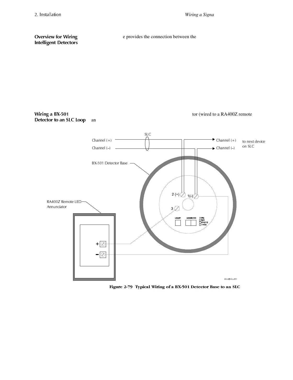
The BX-501 base provides the connection between the SLC and SDX–551, SDX-
551TH, SDX-751, CPX-551, CPX-751, FDX-551R, FDX-551, LPX-751, and IPX-751
intelligent detectors.
1. Connect the communications loop to terminal 1 (–) and terminal 2 (+) on the
detector mounting base.
2. If using an RA400Z Remote LED Annunciator: (a) connect the RA400Z positive
terminal to BX-501, B501, or B71-LP terminal 3; and (b) connect the RA400Z
negative terminal to BX-501 terminal 1 base.
3. Set the detector address on the head with a small, slotted screwdriver. Mark this
address on the base and on the head.
4. Install the intelligent detector head.
:LULQJ D %;
'HWHFWRU WR DQ 6/& /RRS
Figure 2-79 shows typical wiring of a BX-501 detector (wired to a RA400Z remote
annunciator) connected to an SLC loop:
)LJXUH 7\SLFDO :LULQJ RI D %; 'HWHFWRU %DVH WR DQ 6/&
%; 'HWHFWRU %DVH
&KDQQHO
&KDQQHO ²
WR QH[W GHYLFH
RQ 6/&
&KDQQHO
&KDQQHO ²
5$= 5HPRWH /('
$QQXQFLDWRU
6/&
www.PDF-Zoo.com
 Loading...


