5
Table of figures
Figure 4.1: Start screen when inserting in the software CD ................................................................... 20
Figure 4.2: Installation of bluetooth software, step 1 ............................................................................. 20
Figure 4.3: Installation of bluetooth software, step 2 ............................................................................. 21
Figure 4.4: Installation of bluetooth software, step 3 ............................................................................. 21
Figure 4.5: Installation of bluetooth software, step 4 ............................................................................. 21
Figure 4.6: Installation of bluetooth software, step 5 ............................................................................. 22
Figure 4.7: Installation of bluetooth software, step 6 ............................................................................. 22
Figure 4.8: Installation of bluetooth software, step 7 ............................................................................. 23
Figure 4.9: Installation of bluetooth software, step 8 ............................................................................. 23
Figure 4.10: Installation of bluetooth software, step 9 ........................................................................... 24
Figure 4.11: Installation of bluetooth software, step 10 ......................................................................... 24
Figure 4.12: Installation of bluetooth software, step 11 ......................................................................... 25
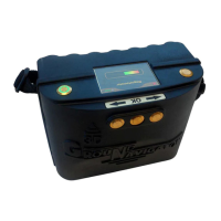
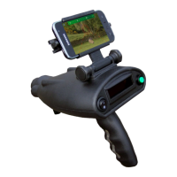
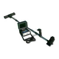
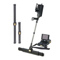
Figure 5.1: 3D Ground Navigator with control unit and Super Sensor ................................................... 28
Figure 5.2: Control elements of the top and front panel ......................................................................... 29
Figure 5.3: Control elements on the bottom panel .................................................................................. 30
Figure 5.4: Touch areas of the display .................................................................................................... 31
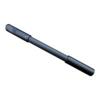
Figure 5.5: Super Sensor with LED orbit ................................................................................................ 32
Figure 5.6: Bluetooth headphones with accessories ............................................................................... 33
Figure 6.1: Charging the internal battery of the control unit ................................................................. 36
Figure 6.2: Connecting the Super Sensor ............................................................................................... 36
Figure 6.3: Connecting the Power Pack (optional) .................................................................................. 37
Figure 6.4: Pocket the optional Power Pack (optional) ............................................................................ 37
Figure 6.5: Power on your control unit and get ready to scan ................................................................ 38
Figure 7.1: Splash screen during boot-up ............................................................................................... 40
Figure 7.2: Display representation in operating mode "Ground Scan" ................................................... 44
Figure 7.3: "Zig-Zag" scanning (left) and "Parallel" scanning (right) ...................................................... 45
Figure 7.4: Position of the Super Sensor during a measurement ............................................................ 48
Figure 7.5: Pinpointing with Super Sensor ............................................................................................. 48
Figure 7.6: Signature of a ferromagnetic metal target ........................................................................... 49
Figure 7.7: Signature of a non-ferromagnetic metal target .................................................................... 49
Figure 7.8: Signature of a non-metallic target ........................................................................................ 49
Figure 7.9: Probe should always point downwards and should not be turned ........................................ 51
Figure 7.10: Pivoting or turning the probe falisifies the measurement .................................................. 51
Figure 7.11: Pairing Bluetooth headphones ............................................................................................ 54
Figure 7.12: Information screen ............................................................................................................. 54
Figure 7.13: Changing Bluetooth address ............................................................................................... 55
Figure 7.14: Reset to factory defaults ..................................................................................................... 55
Figure 7.15: Back screen ........................................................................................................................ 56
Figure 8.1: Starting position of a scan area ............................................................................................ 58
OKM GmbH
www.okmmetaldetectors.com