5-24
Okuma America Corporation
CONSTRCONSTR
CONSTRCONSTR
CONSTR
UCTIONUCTION
UCTIONUCTION
UCTION
Rev. 8-21-01
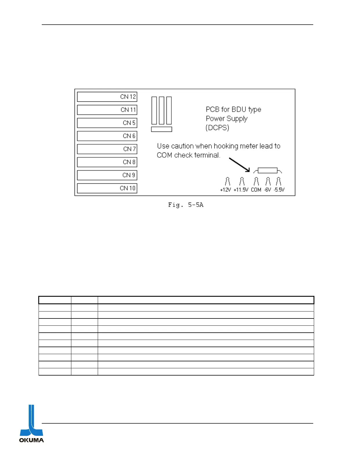
There are five check terminals on the lower right side of this same PCB board. The voltage
levels that should be measured are shown below the individual check terminals. The middle
terminal is the common and extreme caution should be taken when attaching a lead to this
terminal because there is a 100K ohm 2 watt (green) resistor right above this terminal that has
220 VAC going through it! Figure 5-5A illustrates how close the resistor is to the check termi-
nal.
The BDU type power supply has a “Push Switch” on it which is used to discharge the C5 capaci-
tor before doing any work on it. Do not press this push button when power is still being sup-
plied to the drives. The BLD and BLIID have an indication lamp that remains lit until the
capacitor is discharged. Wait until this lamp is off before doing any work on the drives.
The SVC board on the BDU-A drive amplifier has ten LED indicators on it. The following table
describes what they mean.
Description of LED’s on the SVC board of a BDU-A type drive amplifier.
LED Color Description
PH Loss Red Phase loss in 220 VAC supplied to the BDC board.
VR Loss Red The + or - 12 VDC and/or 5 VDC has dropped below specifications.
IOCM Red Instantaneous Over Current in the Motor.
IOCS Red Instantaneous Over Current in the Servo amplifier.
LV Red Low Voltage
HV Red High Voltage
OC Yellow Over Current-Is triggered at 10 % of IOCM trigger level.
SAT Yellow Saturation-Drive amplifier received a heavy load.
SAOP Yellow Sub Amp Operation-Turns off when machine ready signal is received.
PSON Green Power is supplied to drive amplifier.
 Loading...