5-25
Okuma America Corporation
CONSTRCONSTR
CONSTRCONSTR
CONSTR
UCTIONUCTION
UCTIONUCTION
UCTION
Rev. 8-21-01
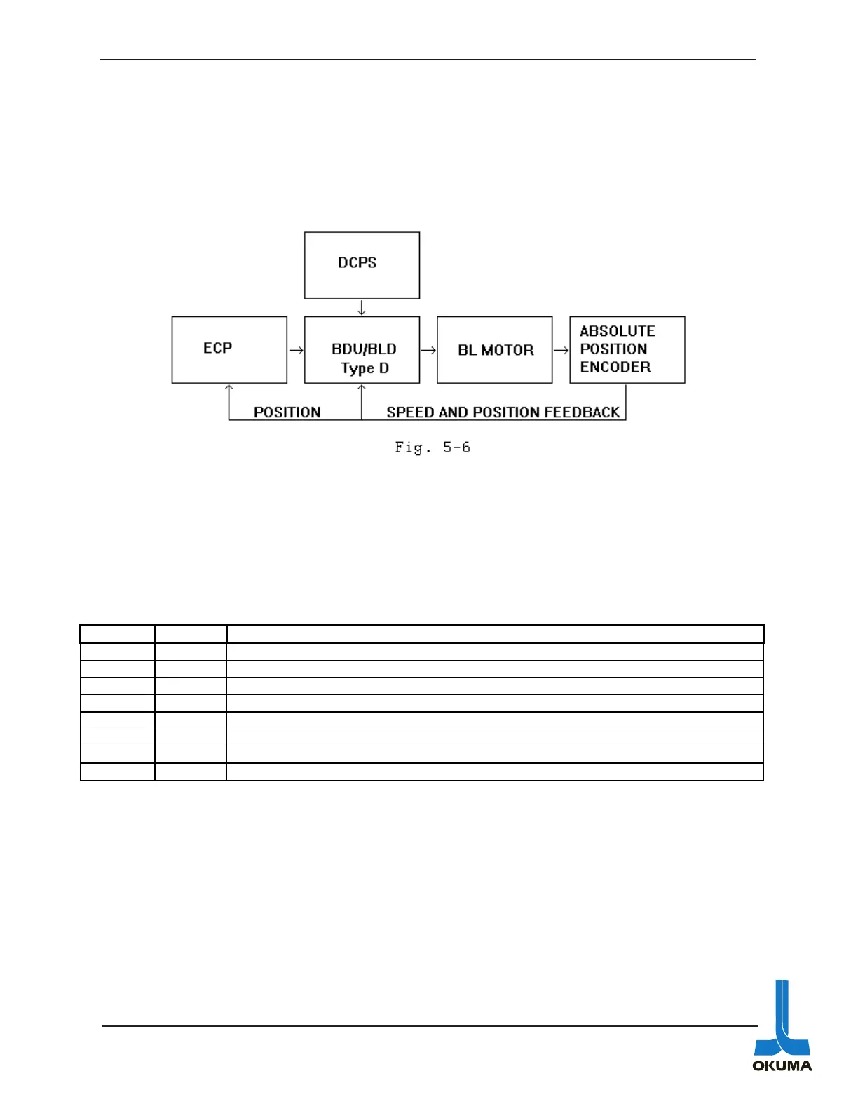
The BDU-D type axis drive as mentioned previously is used for controlling the ATC magazine
and the APC pallets. The two big differences about this drive compared to the BDU-A is the
command signal is an analog signal and comes from the ECP board. A block diagram of this
servo system can be seen in Figure 5-6.
The BDU-D drive amplifier is composed of four parts: base unit, BDC board, SVC-1 board, and
SVC-2 board.
The SVC-1 board has eight LED indicators on it. The following table describes what they mean.
Description of LED’s on SVC-1 board of a BDU-D drive amplifier.
The SVC-2 board has the same LED indicators as the SVC board on a BDU-A drive amp. Refer
to the table for the SVC board on the previous page for a description of these LED’s.
LED Color Description
D0 Yellow Used for inspection purposes during assembly.
D1 Yellow Used for inspection purposes during assembly.
D2 Yellow Used for inspection purposes during assembly.
APA Red This LED turns on whenever RCON and RAPA do not match.
MPR Red This LED turns on whenever the MPR data from the encoder is abnormal.
E8 Red This LED turns on whenever the E8 data from the encoder is abnormal.
CPU Green CPU is in normal operation. CPU is running.
ALA Red This Alarm LED turns on when the APA,MPR, or E8 LED turns on.

 Loading...