6-20
Okuma America Corporation
DIAGNOSTICSDIAGNOSTICS
DIAGNOSTICSDIAGNOSTICS
DIAGNOSTICS
Rev. 8-21-01
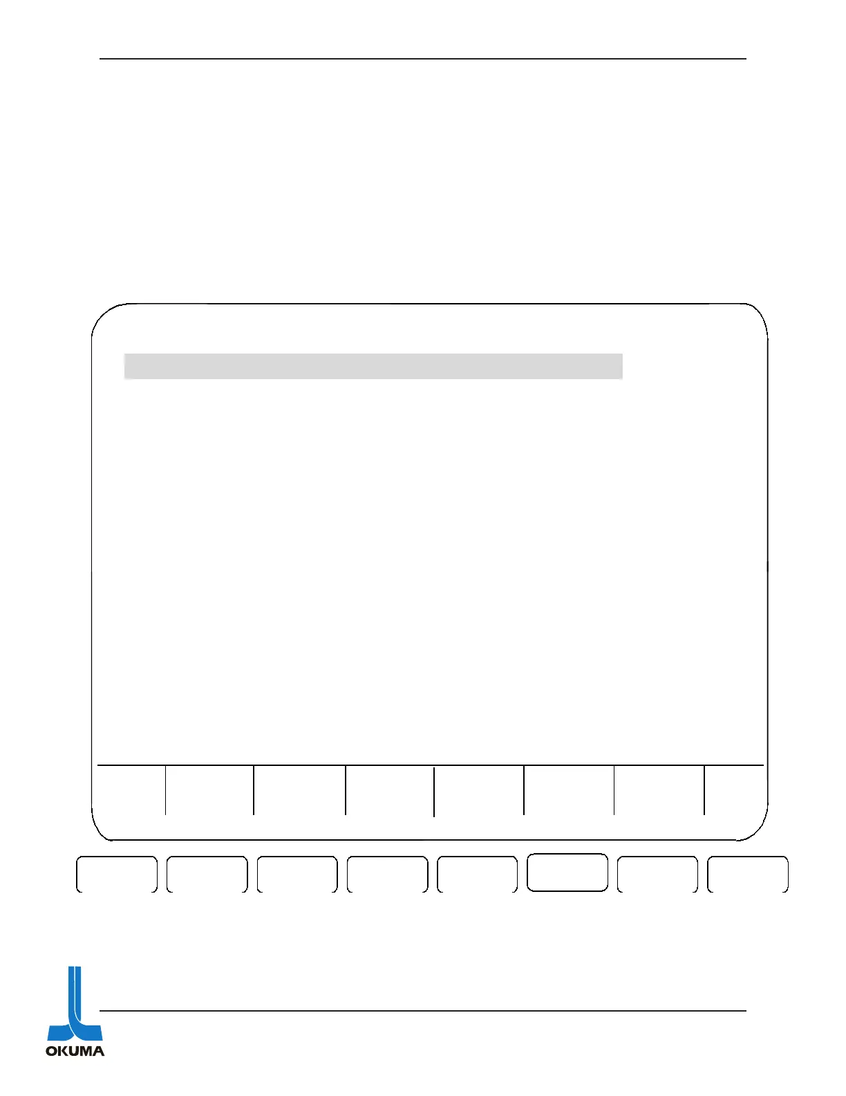
The following is an example of how an alarm is displayed on the 2nd line of the CRT when an
alarm occurs. The 1st group of asterisk on the left display the alarm number and axis code. This
axis code indicates which axis the alarm is being generated by if any. To the right of the alarm
number and axis code, the alarm level is displayed followed by a message. Then to the far right
is the alarm code. This code is in a hexadecimal format and sometimes needs to be converted to
a binary format to decipher the source of the problem. Look up the alarm in the “Alarm & Error
List” manual for an explanation of the alarm.
F3 F7 F8
F1 F2
F6
F5F4
MDI OPERATION N 0
****-** ALARM-* Alarm Message Alarm Code
BLOCK
DATA
DATA
INPUT
ACTUAL
POSIT
SEARCH
CHECK
DATA
Part
Pro
ram
EXTEND
XA 20.0378
ZA 45.0496
XB 25.0267
ZB 40.0845
 Loading...