5-6
Okuma America Corporation
CONSTRCONSTR
CONSTRCONSTR
CONSTR
UCTIONUCTION
UCTIONUCTION
UCTION
Rev. 8-21-01
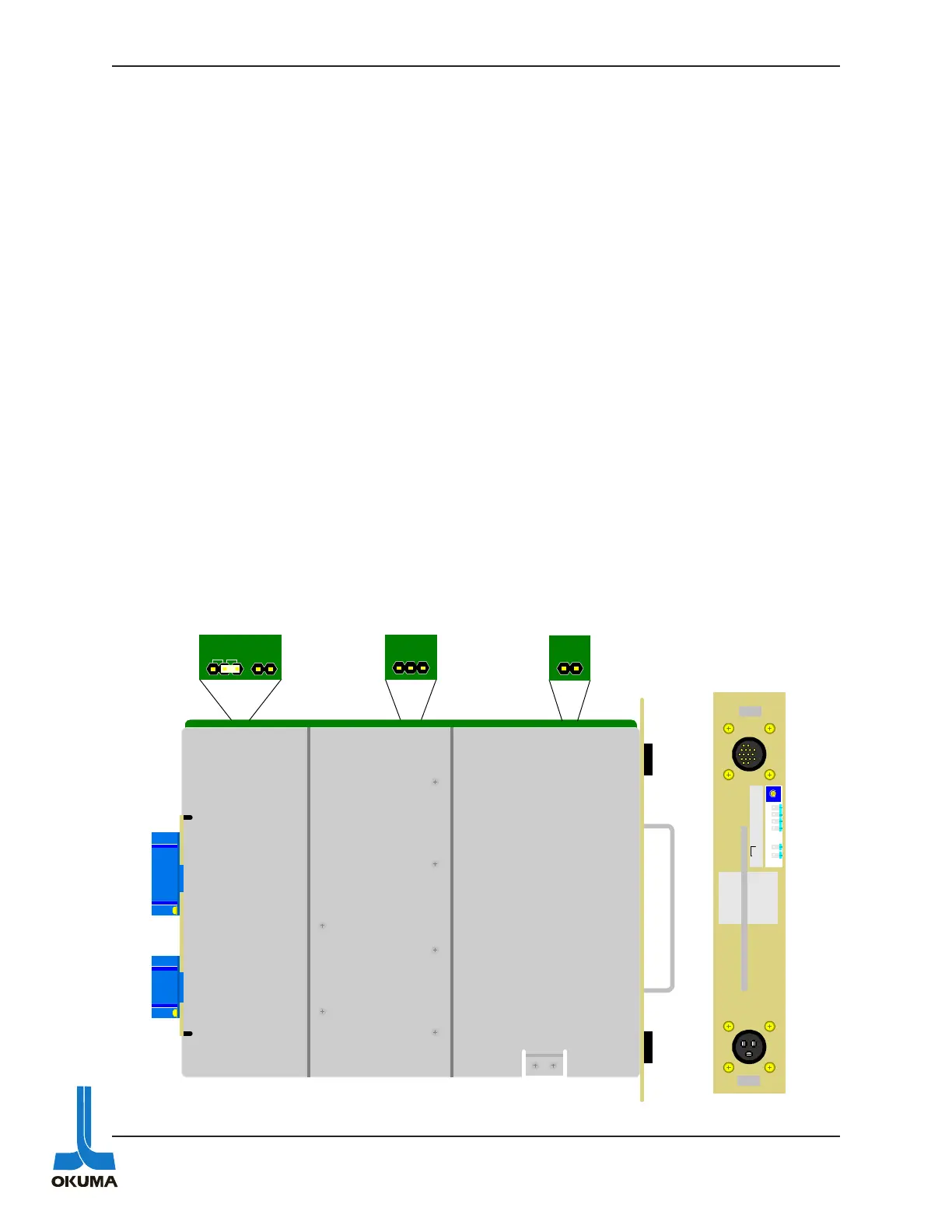
The RHP power supply has two pins that can be “jumpered” to disable the ISO under voltage
alarm function. These two pins should only be jumpered for troubleshooting purposes. The
location of these two pins can be seen in figure 5-2. Make sure to remove this jumper after
checking this power source.
Only the + 5 volts supply is adjustable on these CPU power supplies. It is factory set at 5.1
volts. If an adjustment is necessary, measure the voltage between the check terminals “0V” and
“+5V”. Make sure to check this voltage under a full load (machine on). When making adjust-
ments, make sure to turn the “+5V adjustment potentiometer very slowly.
The low voltage detection alarm for the 5 volt supply turns on when approximately 4.6 volts is
detected. If this alarm occurs, proper adjustment cannot be made without disabling this low-
voltage detection function. On the non-rack type CPU power supplies, a toggle switch is used to
disable this 5 volt low-voltage alarm detection function. On the rack type power supplies, the
machine must be powered off and the power supply has to be removed from the control rack.
Once the CPU power supply is removed from the rack, the “shorting jumper” on the PCB has to
be moved to the UV OFF position as shown below.
Once the adjustment procedure is completed, make sure to move the shorting jumper back to the
UV ON position. This will ensure that the 5 volt monitoring circuit is re-activated.
Fig. 5-2
UV2
UV1
VBCOM
UV
ON
OFF
COM
V1
ISO
UV OFF
OKUMA
OPUS 5000 RHP
POWER SUPPLY
+5V
ADJ .
+5V
0V
+12V
+24V
0V
+24V
ISO
CN2
CN1