Pin hole image slioi~l(l
be contained
within
this circle.
*
Cross hair of
KNOI)?Y
Fig.
9-1
WHKIOX
B-KN0003
LB
objective
f
l
I
w
Specimen
--
I
Condenser
rn
9-1-2
Bring down Microscope Stand on
its
front
as
shown in Fig. 9-1. Recommended to apply
soft cloth or some other packing material
between Nosepiece and desk surface.
9-1-3
Looking through Special Centering Telescope
KN0029, rotate
its
front lens portion (helicoid)
to focus on the cross hairs.
9-1-4
Slide the front lens portion of
KN0029 back
and forth to
focus on the Pin Hole of B2-
I<C0002.
STANDARD: 1 division of cross hairs of
I<N0029.
;I)
I1 tile S1-ANDAR
D
is not met (deviation
c?xct:eds 1 tlivisiotis), adjust position of
1I1(2 Ligllt Exit Utiil.
I,)
Alie~ loosening Screws 3PUK2.6x6SA on
Mirror
Mourlt Unit ZJ538400, adjust the
pillhole Image within 1 division on the
cross hair of
KN0029.
Tighten Screws 3PUK2.6x6SA.
9-2 Assemble the Electrical Base with Microscope
Stand by tightening three Srews
AB6x25SA.
9-3 Check and adjustment of Fine Adjustment
sensitivity
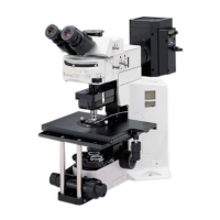
9-3-1 Use the following jigs on the Microscope
Standard as shown in Fig. 9-2:
B-KN0003:
Standard jig for tube length
LB40x objective
WHKIOX or
WKlOx
Condenser
Ordinary specimen
Fine adjustment sensitivity
STANDARD: Within
4p (within 2 di-
visions on knob scale)
NOTE:
If no B-KN0003
is
available use any
observation tube instead.
Fig.
9-2
-49-

 Loading...