45
MX63/MX63L
45
Make a copy of this flow chart and diagram, and place it near the microscope so that you can use it when
operating the microscope.
Use the stage MX-SIC1412R2 or MX-SIC8R that is applicable for transmitted light observation.
The transmitted light illumination range of the applicable stage is described below.
MX-SIC1412R2 * X: 356 mm Y: 284 mm
MX-SIC8R X: 189 mm Y: 189 mm
* When the transmitted light illumination unit (MX-TILLA) is used, it is
required to attach a stopper that limits the Y-axis stroke to 261 mm because
the condenser is protruded. For details, see “Attaching the Y-stroke limit
stopper" on page 89.
3
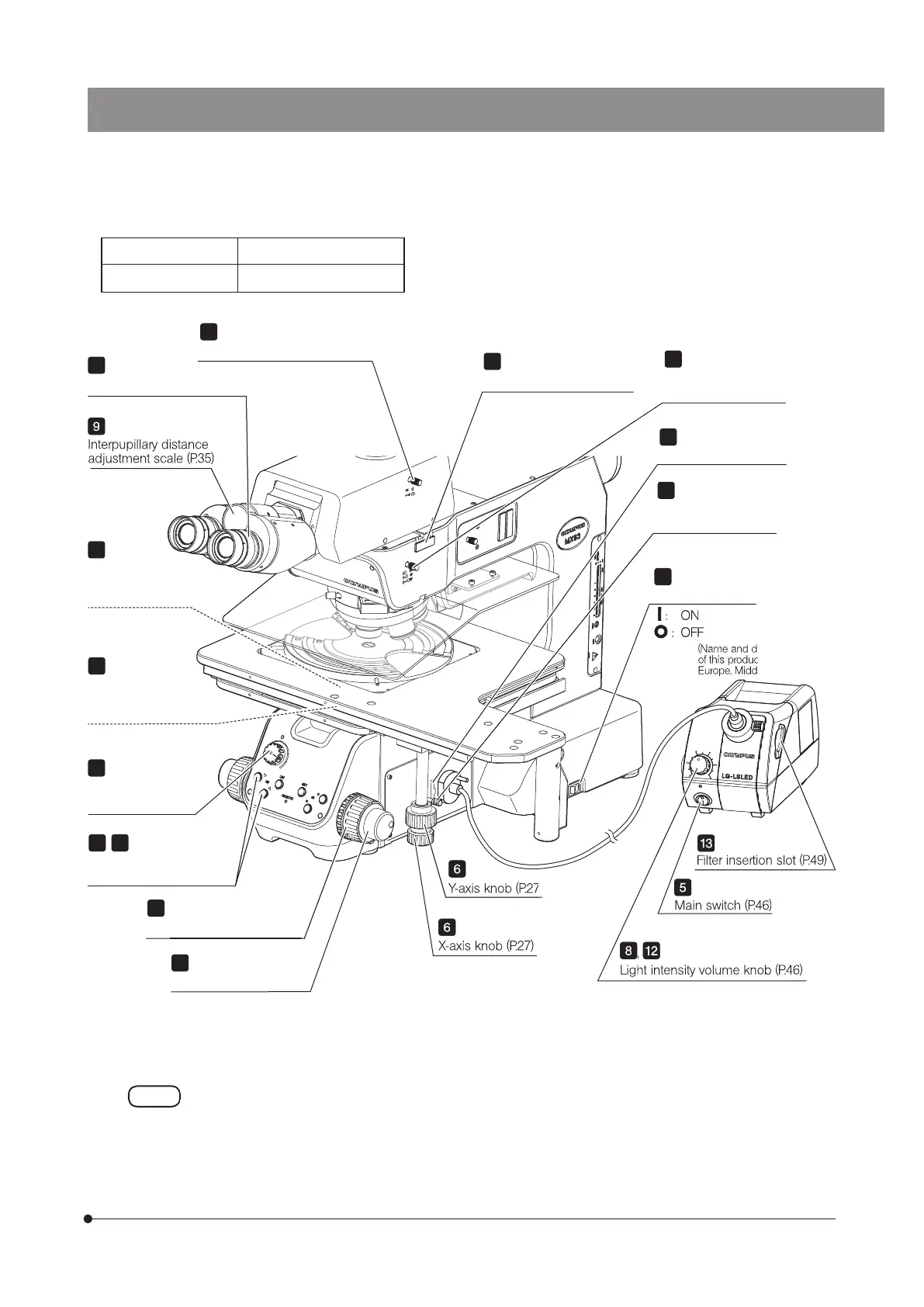
Light path selection knob (P.26)
9
Interpupillary distance
adjustment scale (P.35)
1
Light intensity knob
(P.46)
7
,
11
Objective selection button
(P.28)
6
Y-axis knob (P.27)
X-axis knob (P.27)
4
Analyzer insertion slot (P.51)
Coarse focusing knob (P.29)
Fine focusing knob (P.29)
(detachable)
Filter insertion slot (P.49)
Aperture diaphragm
lever or aperture
diaphragm ring (P.48)
14
Field diaphragm lever
(MX-TILLB) (P.47)
Condenser height
adjustment ring
(MX-TILLB) (P.47)
5
Main switch (P.46)
Filter insertion slot (P.49)
(Name and detail specifications
of this product might differ in
Europe, Middle East and Africa.)
Observation light path
selection knob (P.25)
Diopter adjustment ring (P.35)
Main switch (P.46)
: ON
: OFF
8
,
12
Light intensity volume knob (P.46)
(Name and detail specifications
of this product might differ in
Europe, Middle East and Africa.)
of this product might differ in
Europe, Middle East and Africa.)
of this product might differ in
Filter insertion slot (P.49)
Filter insertion slot (P.49)
Filter insertion slot (P.49)