OMEM710 Hardware Manual 2v11
10
The physical input and output pins for each function are in some cases fixed (eg Coolant
Temperature sensor must always be on the same physical pin) but many are selectable. The
physical pins have names based on their normal output type, but the names do not necessarily tell
the user what they are being used as. The wiring section of the manual gives suggested pin-outs for
most engines but some will need to be decided by the user. If you are in any doubt then please
contact Omex. The ECU needs to be told which pins are being used for which functions. Much of
this will be set in startup calibrations from Omex.
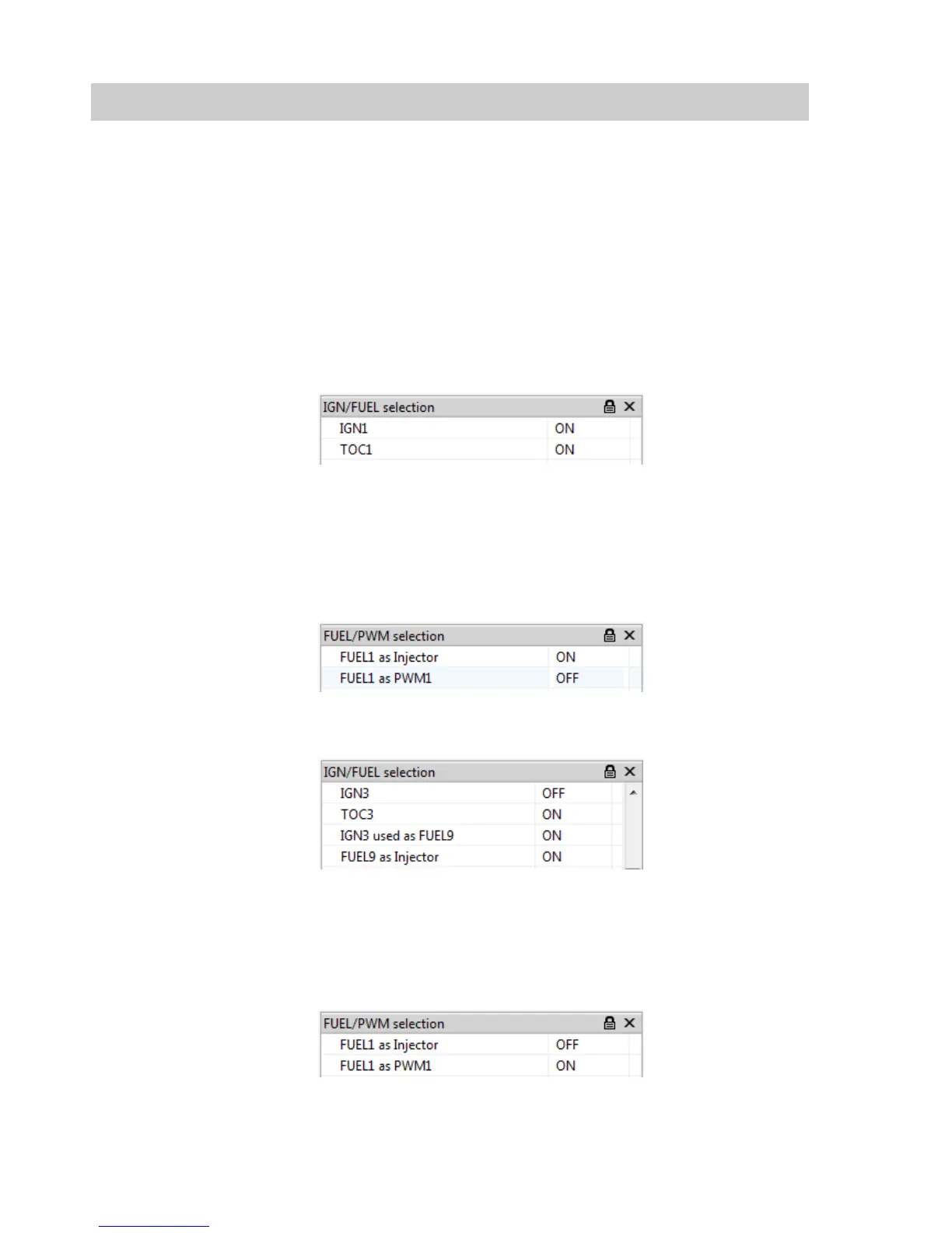
4.1 Ignition Coils
Ignition coils may be controlled on any of the IGN pins. To set an IGN pin as a coil driver it must
have the IGNx and TOCx ON.
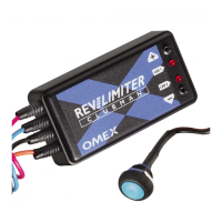
4.2 Fuel Injector
Injectors may be controlled by any of the FUEL pins and IGN3, IGN4, IGN5, or IGN6.
To set a FUEL pin as an injector driver it must have the FUELx as injector ON and FUELx as PWM
OFF.
To set IGN3, IGN4, IGN5, or IGN6 pin as an injector driver they must have the TOCx and IGNx as
FUELx ON. IGNx must be OFF.
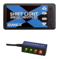
4.3 PWM Devices
PWM devices (such as idle motors, boost solenoids etc) may be controlled by any of the FUEL pins.
To set a FUEL pin as a PWM driver it must have the FUELx as PWMx ON and FUELx as injector
OFF.
Controls are then applied to these activated PWM outputs using the Setup | Output Pin Allocation
| PWM Outputs options group.