EasyManua.ls Logo

OMEX OMEM710 - ECU Connector Pin Assignments

OMEX OMEM710
72 pages
Print Icon
To Next Page IconTo Next Page
To Previous Page IconTo Previous Page
Loading...
OMEM710 Hardware Manual 2v11
66
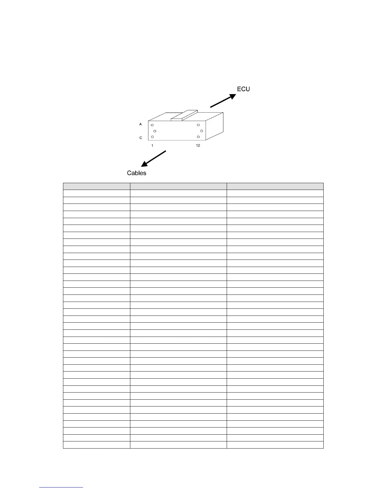
29.2 ECU Connector Pins
It is occasionally neccessary whilst fault finding to trace through your wiring harness to check
continuity. The following are the pin-outs for the ECU plug as found on the end of the wiring
harness. Where there are two colours, the first is the main colour and the second is the tracer eg
Yellow violet yellow with violet tracer
number
colour code
output name
1A
Yellow black
IGN1
2A
Yellow violet
IGN6
3A
Brown pink
FUEL8
4A
Red
Battery power
5A
Black
Power ground 1
6A
Grey
Sensor ground
7A
Black screened red
Crank sensor
8A
Timing ground
9A
White violet
Coolant temperature sensor
10A
White yellow
MAP2
11A
Red screened red
Cam Sensor
12A
Yellow grey
IGN2
1B
Yellow orange
IGN4
2B
Yellow green
IGN5
3B
Brown violet
FUEL6
4B
Brown black
FUEL1
5B
Brown green
FUEL5
6B
Blue white
MAP1
7B
Black
Power ground 2
8B
Brown grey
FUEL7
9B
White green
Air temperature sensor
10B
Blue
Knock sensor
11B
White orange
Oxygen sensor 2
12B
Yellow red
IGN3
1C
Blue grey
HIGHSIDE2
2C
Brown orange
FUEL4
3C
Brown yellow
FUEL2
4C
5C
Blue black
HIGHSIDE1
6C
Brown red
FUEL3
7C
White red
Oxygen sensor 1
8C
Orange
Throttle position sensor
9C
Pink
5V out
10C
Red Blue
Road speed sensor
11C
White pink
ALT POWER
12C
Blue yellow
Tacho

Related product manuals