OMEM710 Hardware Manual 2v11
21
5.11 Cam2 Sensor
The Cam2 sensor is used for some engines, typically twin VVC engines.
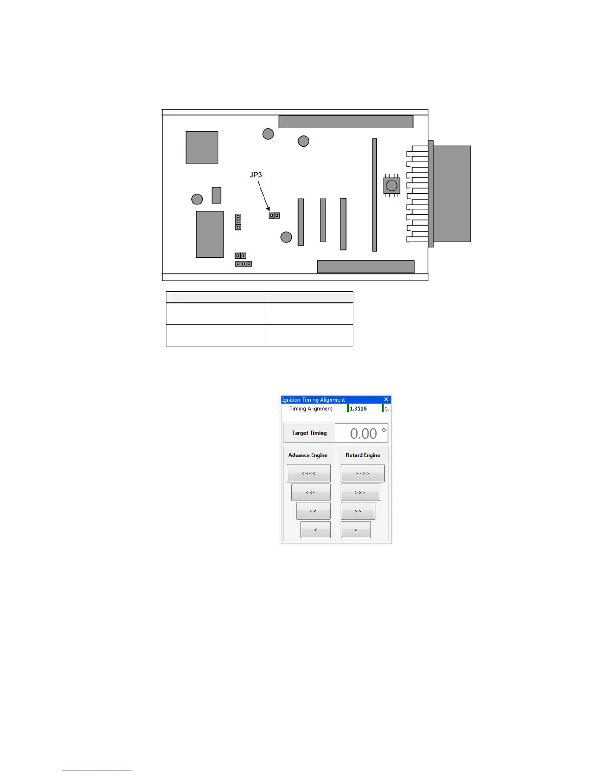
5.12 Ignition Timing Alignment
The ECU recognises the engine position by a missing or extra tooth on a pattern of evenly spaced
teeth. Different manufacturers have this reference in a different place on the trigger wheel so the
ECU needs to have adjustment for this. The numbers are known for most manufacturers and will be
set in the start-up calibration but if they are unknown or if you are using an Omex external 36-1
wheel, you will need to find this value yourself. To find this value you will need a strobe light and an
accurate TDC mark on the engine.
Hold the engine at 2000-3000 rpm (ie out of the idle condition where the ignition timing is stable)
Check the engine speed shown on the strobe light. Most strobe lights will see the wasted spark
on DIS systems and so will show double engine speed and so also double ignition timing. If this
is the case then halve all ignition timing figures shown on the strobe light.
Check the ignition timing with a strobe light and compare this number to the number in Target
Timing.
If the engine is retarded compared to Target Timing (the strobe light shows a lower value) then
advance the engine. If the engine is advanced compared to Target Timing (the strobe light