OMEM710 Hardware Manual 2v11
18
Hall Effect
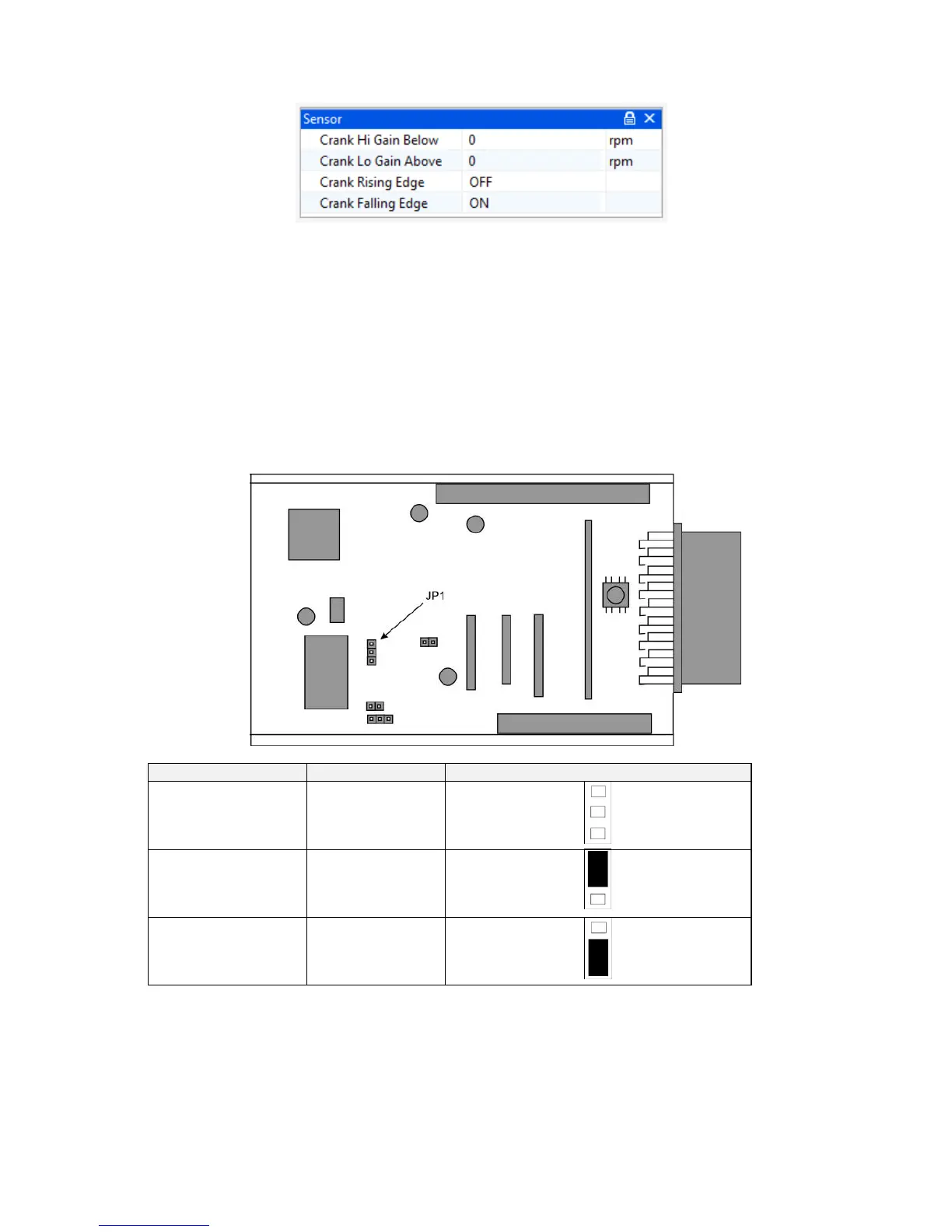
Hall effect sensors require values of 0 for the high and low gain settings as their output is the same
amplitude regardless of engine speed.
Hall Effect sensors can use either the rising or falling edge, though typically the falling edge would
be used.
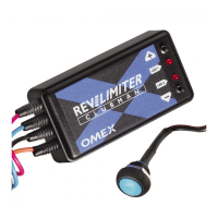
Jumpers
To allow for different input ranges of the crank sensors, physical jumpers need to be set. The
following diagram shows an aerial view of the ECU board with the main wiring connector on the
right-hand side.
5.9 Trigger Wheel
The pattern of teeth on the crank pulley or flywheel that the crank sensor faces is known as a trigger
wheel. The pattern is evenly spaced teeth with missing or extra teeth as reference points. As
different manufacturers use different trigger patterns, the ECU is programmable to suit. The
information required in the ECU for many of the popular patterns is already known, some of which
are listed below. If you have a different pattern on your engine please contact Omex for advice.