OMEM710 Hardware Manual 2v11
69
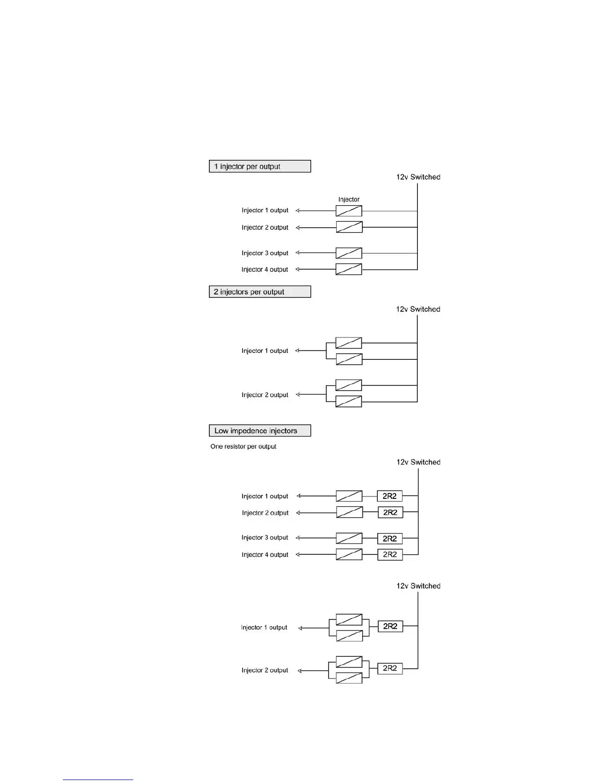
The following diagram shows examples of how injectors should be wired for a 4 cyl engine. Firstly is
the case of one injector per output ie sequential fuelling, then two injectors per ouput ie semi-
sequential. When paired, you should ensure that the correct injectors are joined. If standard 4 cyl
firing of 1342, then 1+4 should be paired, and 2+3. If the injectors have an impedence of less than
6ohms they require ballast resistors. Each ballast resistor should cover two injectors only.