6 - 39
6 Drive Programming Commands
Drive Programming User’s Manual (I580-E2)
6-6 I/O Control Commands
6
Example
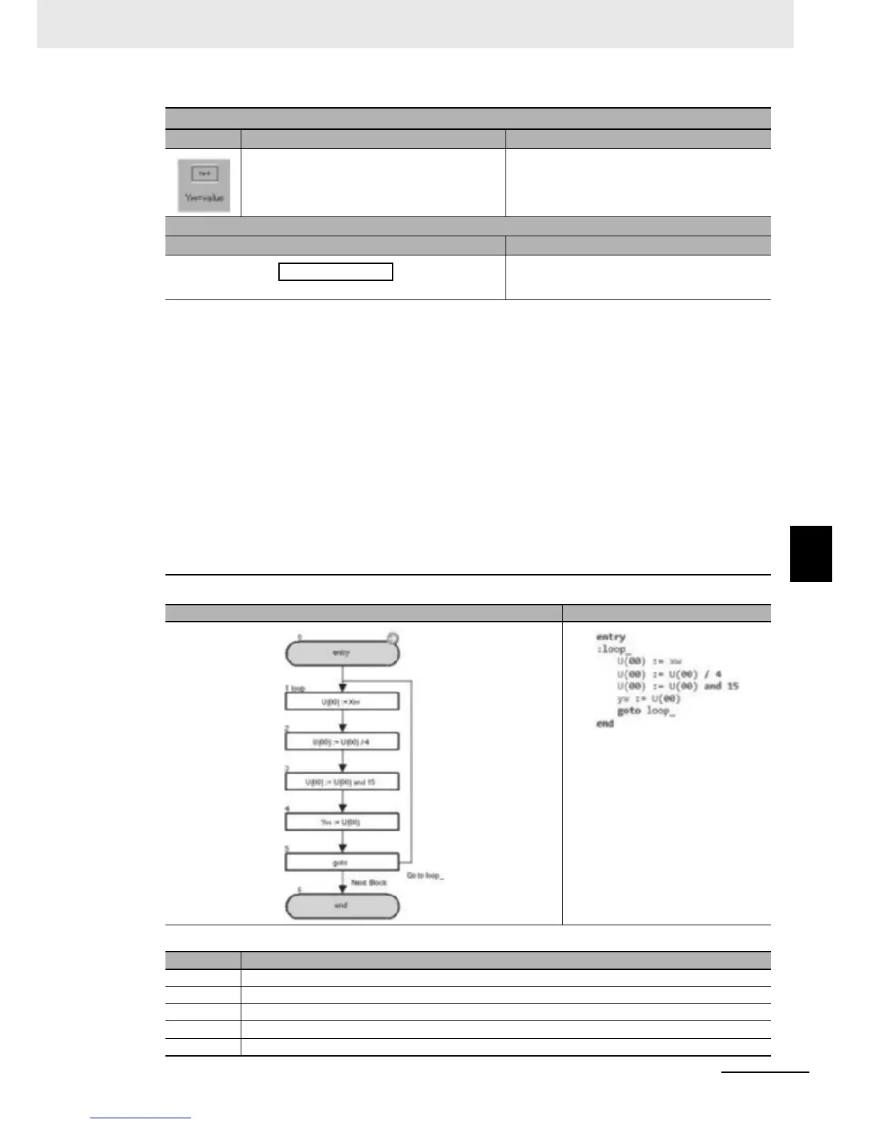
In the above example, the status of the input terminals X(02) to X(05) is captured and output to the output terminals Y(00) to Y(03).
Yw value
Command Description Argument
Outputs data to the output terminal variable in
units of words.
Reflect each bit in corresponding output.
Value: any variable or constant
Format
Flowchart method Text language method
Yw : <value>
Note The output terminal variable is a variable that controls the status of the inverter's output termi-
nal. The following settings are required. The numerical order of the output terminal variables
follows the numerical order of the set general-output numbers.
MX2: Set the Multi-function Output P1 and P2 Selection (C021 and C022) and the Multi-function Relay
Output (MA, MB) Function Selection (C026) to 44 to 46 (MO1 to MO3: General-purpose output).
RX: Set the Multi-function Output P1 to P5 Selection (C021 to C025) and the Multi-function Relay Out-
put (MA, MB) Function Selection (C026) to 44 to 49 (MO1 to MO6: General-purpose output).
When the data is assigned in units of words, zero is read out for the upper byte data and unset input termi-
nal variables. If there is any setting, the setting is ignored.
<Assignment example>
Yw 1 (bit 0) to Y(00) MO1 (multi-function No. 44)
Yw 2 (bit 1) to Y(01) MO2 (multi-function No. 45)
Yw 4 (bit 2) to Y(02) MO3 (multi-function No. 46)
Yw 8 (bit 3) to Y(03) MO4 (RX only: multi-function No. 47)
Yw 16 (bit 4) to Y(04) MO5 (RX only: multi-function No. 48)
Yw 32 (bit 5) to Y(05) MO6 (RX only: multi-function No. 49)
For details, refer to 5-2 Input/Output Terminal Variables on page 5-5.
Flowchart Text
Block number
Operation
1 Assigns the value of Xw (value of input terminal) to U(00).
2 Divides the value of U(00) by 4 (2-bit right shift) to assign X(02) to bit 0.
3
Performs a logical AND operation on U(00) and 15 (binary: 00001111) and changes the bits higher than X(06) to zero.
4 Assigns U(00) to Yw.
5 Jumps to the block 1: loop_ unconditionally.
 Loading...


