115
Allocations to Slave Units Section 5-2
Unit Number Allocations
Allocating One Unit
Number per Node
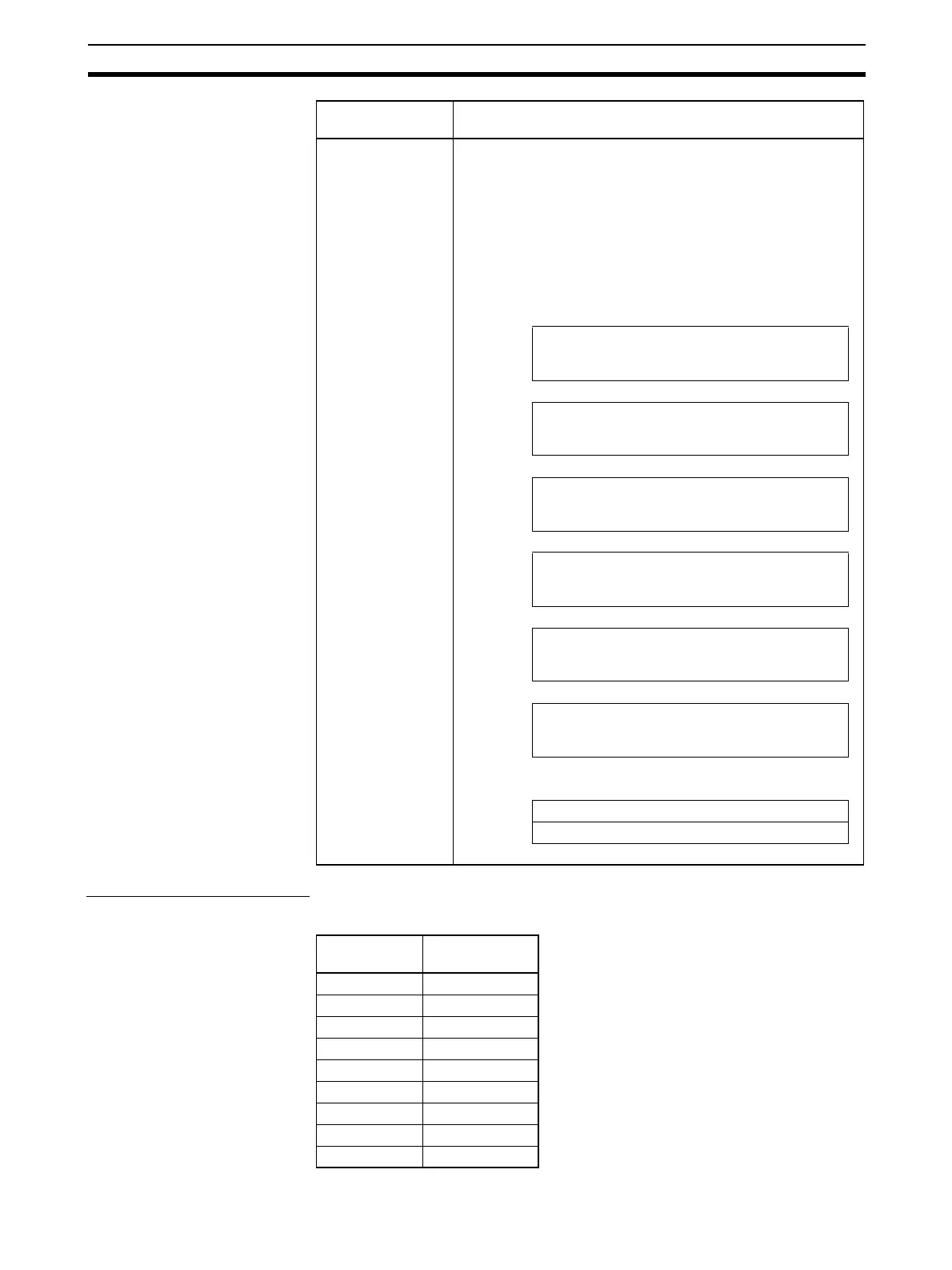
(Communications Mode 8)
CIO 2000 + (10 × Unit No.) to CIO 2009 + (10 × unit No.): Unit No. = 0 to 95)
8 The first addresses for Word Slave input and output data, Bit
Slave bit input and output data, and status data (status, set-
tings, participation, and disconnection) are set using software
settings (areas and addresses) from the CX-Integrator. The
sizes allocated are also set using software settings (number of
nodes) from the CX-Integrator.
Note Words are always allocated to Slave Units in ascending
order from node address 0. Nothing can be allocated to
unused node addresses. If the number of nodes set from
the CX-Integrator is n, then Slave Units are allocated
from node address 0 to n-1.
Words +0
to
+63 max.
Output data (64 words max.)
Slave Unit outputs: 0 to 63
Words +0
to
+63 max.
Input data (64 words max.)
Slave Unit inputs: 0 to 63
Words +0
to
+15 max.
Bit output data (16 words max.)
Bit Slave Unit outputs: 0 to 127
Words +0
to
+15 max.
Bit input data (16 words max.)
Bit Slave Unit inputs: 0 to 127
Words +0
to
+15 max.
Participation Flags and Communications Error
Flags (16 words)
Words +0
to
+31
Bit Slave Participation Flags and Communica-
tions Error Flags (32 words)
The following items are allocated in the Special I/O Unit Area.
+0 Status (1 word)
+1 Parameter settings (1 word)
Communications
mode number
Pattern
First allocated
word
Unit number
setting
CIO 2000 Unit No. 0
CIO 2010 Unit No. 1
CIO 2020 Unit No. 2
CIO 2030 Unit No. 3
CIO 2040 Unit No. 4
CIO 2050 Unit No. 5
:
CIO 2940 Unit No. 94
CIO 2950 Unit No. 95