121
Allocations to Slave Units Section 5-2
■ Analog Input Slave Units
Data to be allocated to the Communications Unit is selected by using one of
the following methods, and it is transferred using remote I/O communications.
■ Default Settings
With the default settings, only the analog input values are set as the I/O data.
Data of 4 words or 8 bytes is allocated to the IN area of the Master Unit.
■ CX-Integrator
The CX-Integrator can be used to assign the analog data in a preset combina-
tion with data such as Status Flags. By using the CX-Integrator, to make the
settings combinations can be selected from a pull-down list.
Example: Analog Data + Top/Valley Detection Timing Flag (Shot Status)
Procedure to Select Analog Data Using the CX-Integrator
1,2,3... 1. Start the CX-Integrator.
2. In the Network Configuration Window, double-click the icon for the Analog
Input Slave Unit. Alternatively, right-click the icon and select Parameters -
Edit from the pop-up menu. The Configuration Window will be displayed.
■ Analog Output Slave Units
An Analog Output Slave Unit has one type of output data that is assigned by
default. No setting is required. Two words (4 bytes) of output data are allo-
cated. The data is allocated as two's complements.
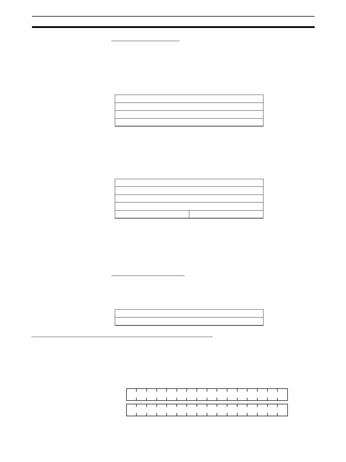
Data Assignment for Word Slave Unit + Expansion Unit
When an Expansion Unit is used, the IN and OUT data of the Expansion Unit
is included in the allocation size of the Unit.
• Sixteen-point Input Slave Unit + Sixteen-point Expansion Input Unit
Two node address areas are allocated: Node address m and node address
m+1 in the IN area.
15 8 7 0
Analog input value for Input 0
Analog input value for Input 1
Analog input value for Input 2
Analog input value for Input 3
15 8 7 0
Analog Data for Input 0
Analog Data for Input 1
Analog Data for Input 2
Analog Data for Input 3
Top Detection Timing Flag Valley Detection Timing Flag
15 8 7 0
Analog output value for Output 0
Analog output value for Output 1
IN area
123456789101112131415 0
171819202122232425262728293031 16