174
CQM1 I/O Link Unit Section 4-10
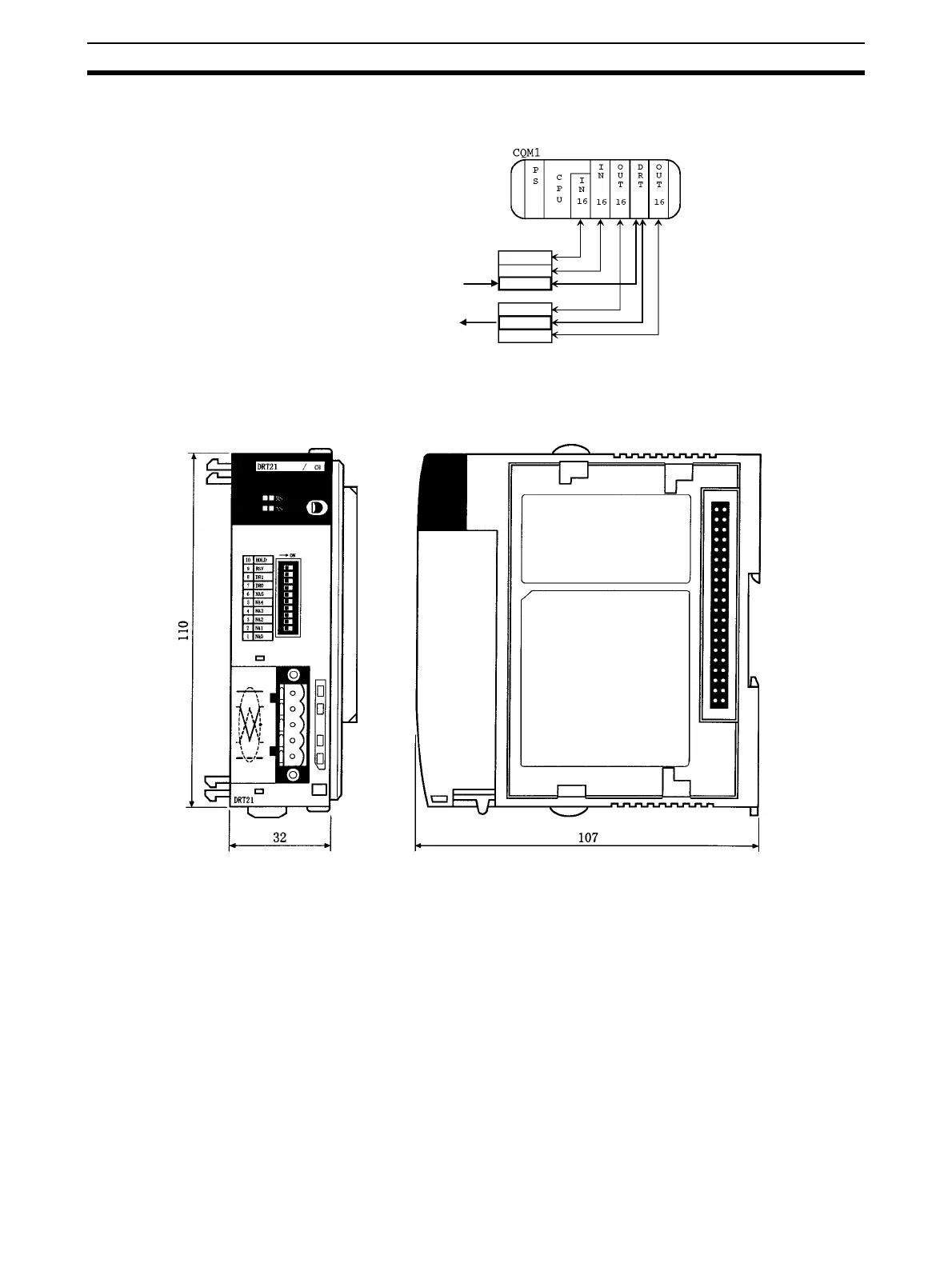
001 for inputs and IR 100 for outputs. The following diagram shows a word
allocation example.
Dimensions The following diagram shows the dimensions for the CQM1-DRT21 I/O Link
Unit. Refer to the PLC’s Installation Guide for the dimensions of the Unit when
it is mounted to the Backplane. (All dimensions are in mm.)
4-10-3 Mounting to Control Panels
The CQM1 I/O Link Unit is assembled with the rest of the Units in the CQM1
PLC for use as one assembled PLC. The CQM1 I/O Link Unit is connected to
the PLC just like any other PLC Unit. Refer to the operation manual for the
PLC for details.
Note No internal power, I/O power, or I/O wiring is required for the CQM1 I/O Link
Unit because it uses internal I/O bits in the CPU Unit to communicate with the
master.
IR 000
IR 001
IR 002
IR 100
IR 101
IR 102
From the Master's
output area
To the Master's
input area
Word allocation
Inputs
Outputs
PS: Power supply unit
CPU: CPU Unit
IN: Input Unit/Terminals
OUT: Output Unit
DRT: I/O Link Unit
(With the cover removed)