97
F3SJ-E/B
User’s Manual
Chapter4 Wiring Examples
Input/Output Circuit and Applications
E
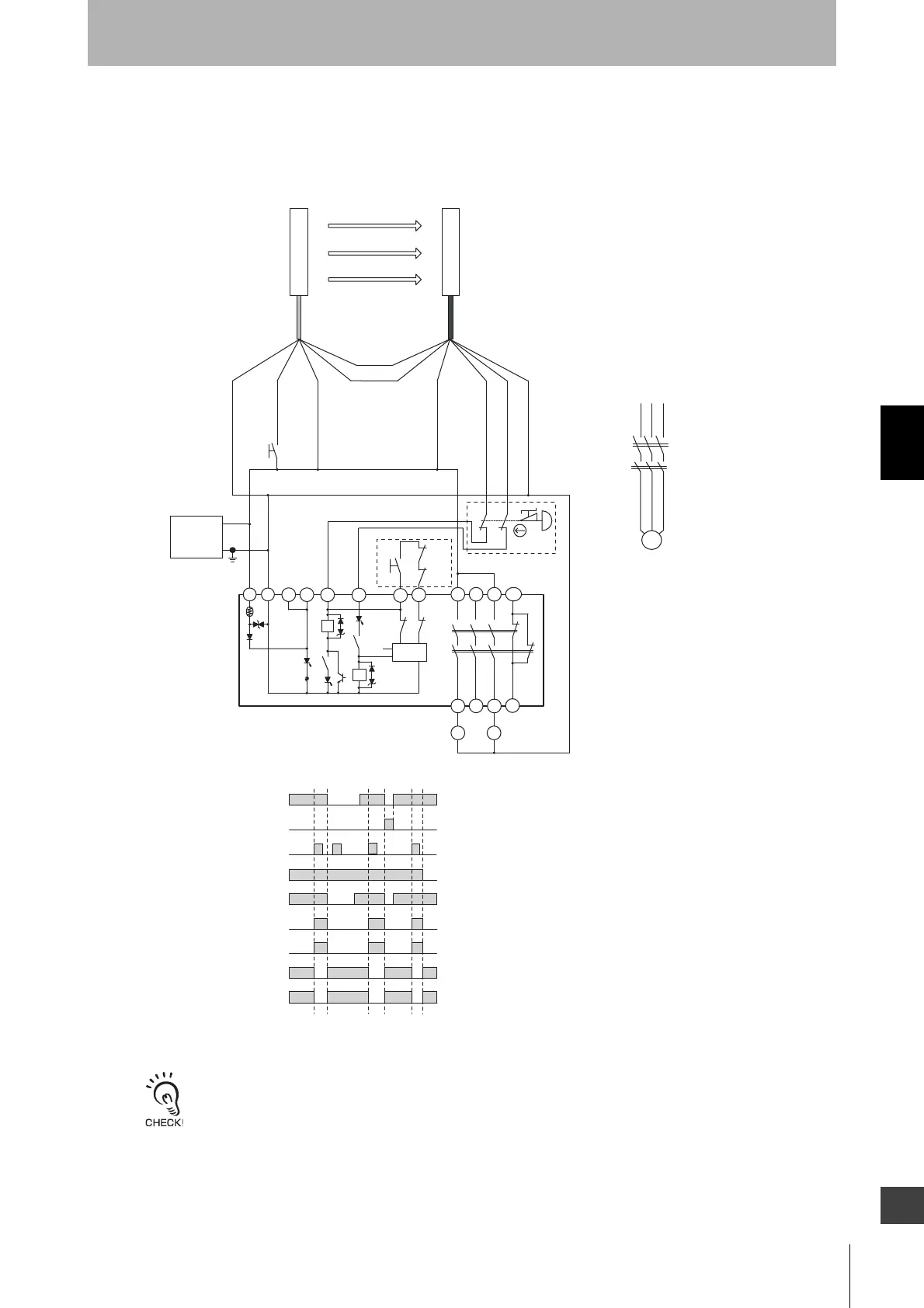
Connecting a F3SJ-E to a G9SB-301-D
•Thin (22.5 mm thick)
Use G9SB-301-B for auto reset with three N.O. and one N.C. contacts.
Use G9SB-200-D for manual reset with two N.O. contacts, or use G9SB-200-B for auto reset with two N.O. contacts.
For more information, visit OMRON's website at http://www.omron.com/
A1
14
24
34
42
41
33
23
13
T32
T31
T11
A2
G9SB-301-D
KM1
KM2
T12
K1
K1
K2
K1
S2
S1
a
K2
Control
Circuit
a
T21
T22
K2
K2
K1
TH
SA
+24 VDC
0 V
KM1,KM2 N.C. contact
Unblocked
Blocked
External test/lockout reset switch
(S1)
Interlock reset switch
(S2)
Safety output
K1,K2 N.O. contact
KM1,KM2 N.O. contact
K1,K2 N.C. contact
Emergency stop switch
(S3)
*1
*1
*1
*1
*1 The G9SB-200-D (17.5 mm thick), with no 33-34 and 41-42, is also available.
*2 If an emergency stop switch is not used, connect safety output 1 to T12
terminal and safety output 2 to T22 directly.
S1 : External test/lockout reset switch
(connect to 0V if a switch is not required)
S2 : Interlock reset switch
S3 : Emergency stop switch (force-opening contact)
(A165E, A22E)
KM1,KM2: Safety relay with force-guided contact (G7SA) or magnetic contactor
M : 3-phase motor
- G9SB-301-D settings
- Manual reset mode
- Using feedback loop
- Using emergency stop switch
*2
11
12
21
22
S3
KM1
KM2
Feedback loop
M
KM1
KM2
Receiver
Emitter
Communication
line (+) (Gray)
Communication
line (-) (Pink)
0 V (Blue)
Test input (Black)
+24 V (Brown)
+24 V (Brown)
Safety output 1 (Black)
Safety output 2 (White)
0 V (Blue)
Power
supply