98
Chapter4 Wiring Examples
F3SJ-E/B
User’s Manual
Input/Output Circuit and Applications
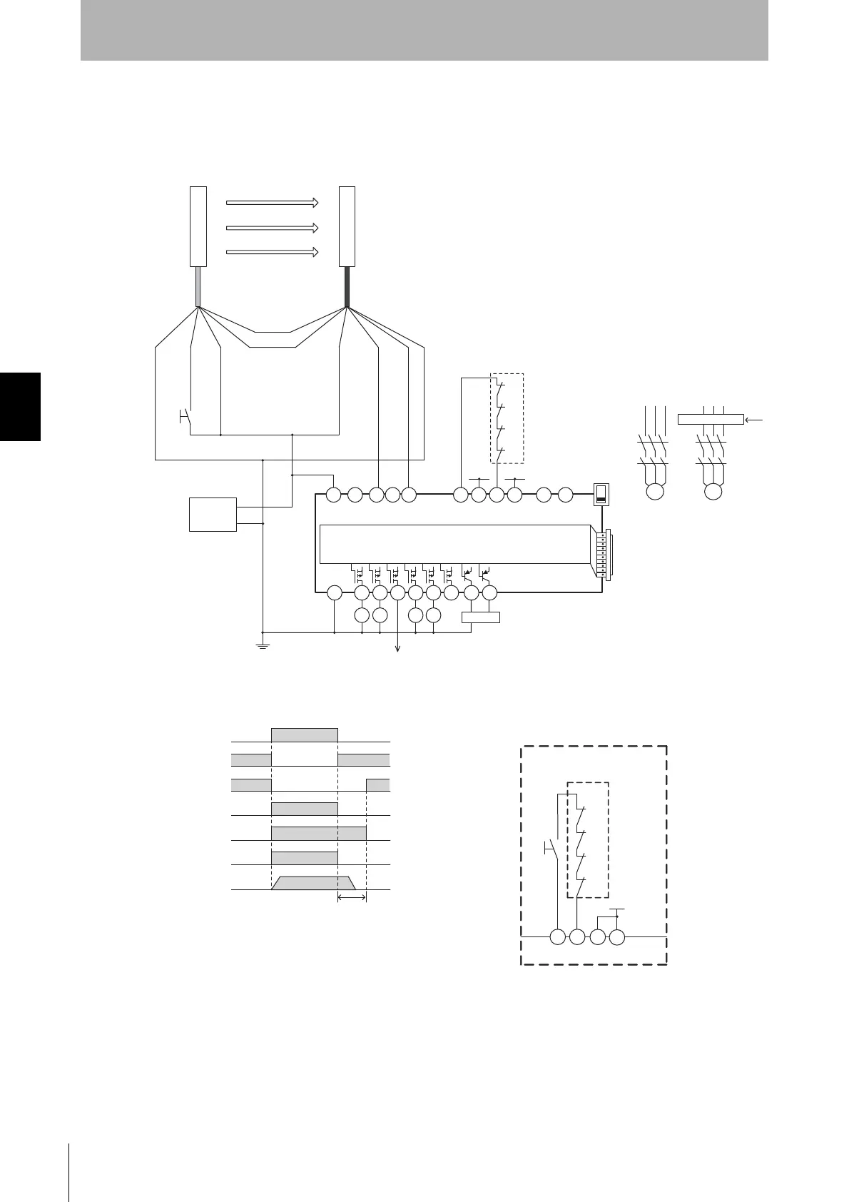
Connecting F3SJ-E to a G9SX-AD322-T15
•Can be configured for partial control and total control
•Can be extended to connect a door switch or a relay unit
+24 V (Brown)
0 V (Blue)
Test input
(Black)
Communication
line (+) (Gray)
Communication
line (-) (Pink)
A1
A2
S14 S24
KM1 KM2
S34 S44 S54
KM3
KM4
L1 X1 X2
T11
KM1
KM2
KM3
KM4
+24 V +24 V
T12 T21 T22 T31
T32
T33
Y1 T41 T42
M1 M2
PLC, etc.
Motor controller
Motor controller
(operation command)
Feedback loop
Open
Model G9SX-AD322-T15
Open Open Open
OFF
AND
KM1
KM2
KM3
S34
KM4
Control circuit
Safety output
KM1,KM2 N.C. contact
KM3,KM4 N.C. contact
KM1,KM2 N.O. contact
KM3,KM4 N.O. contact
Motor operation command
Motor rotation
OFF-delay time
- G9SX-AD322-T15 settings
- Manual reset mode
- Using feedback loop
S1
+24 VDC
0 V
Power
supply
+24 V
T32 T33
Y1
KM3
KM4
T31
KM1
KM2
S2
Wiring for auto reset mode
Feedback loop
S2 : Reset switch
Receiver
Emitter
Safety output 1
(Black)
Safety output 2
(White)
0 V (Blue)
+24 V (Brown)
S1 : External test/lockout reset switch
(connect to 0V if a switch is not required)
KM1 to KM4 : Safety relay with force-guided contact (G7SA)
or magnetic contactor
M1, M2 : 3-phase motor
PLC : Programmable controller
(Used for monitoring -- not related to safety system)