99
F3SJ-E/B
User’s Manual
Chapter4 Wiring Examples
Input/Output Circuit and Applications
E
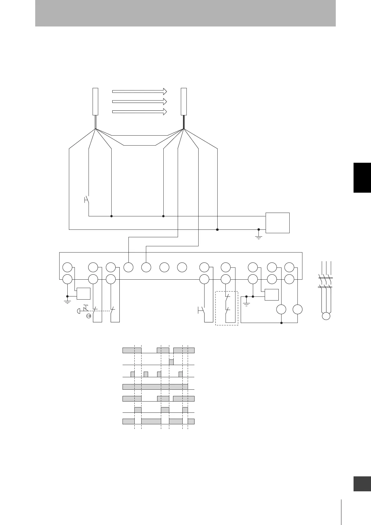
Connecting a F3SJ-E to a G9SP
•Emergency stop switch can be connected
•Door switch, two hand control, single beam sensor, or relay unit can be used in combination with
G9SP.
S3
Test input (Black)
V1 Si0 Si1
G1
GND
S1
T0
11
12
22
21
T1
Si2 Si3 Si4 Si5 Si6 Si7
T2
T3
So0 So1V2
G2
G2
G2
S2
GND
+24 VDC
0 V
Power
supply
M
KM1
KM2
KM1
KM1
KM2
KM2
S1
S2
S3
KM1, KM2
M
: Emergency stop switch
(force-opening contact) (A165E, A22E)
: Reset switch
: External test/lockout reset switch
(connect to 0 V if a switch is not required)
: Safety relay with force-guided contact (G7SA)
or magnetic contactor
: 3-phase motor
Receiver
Emitter
Communication line (+) (Gray)
Communication line (-) (Pink)
0 V (Blue)
+24 V (Brown)
+24 V (Brown)
Safety output 1 (Black)
Safety output 2 (White)
0 V (Blue)
+24 VDC
0 V
Power
supply
KM1,KM2 N.C. contact
Unblocked
Blocked
External test/lockout reset switch
(S3)
Reset switch
(S2)
Safety output
KM1,KM2 N.O. contact
Emergency stop switch
(S1)
+24 VDC
0 V
Power
supply
- G9SP settings
- Manual reset mode
- Using feedback loop
Feedback loop