28
Chapter2 Description of Functions
F3SJ-E/B
User’s Manual
System Configuration and Functions
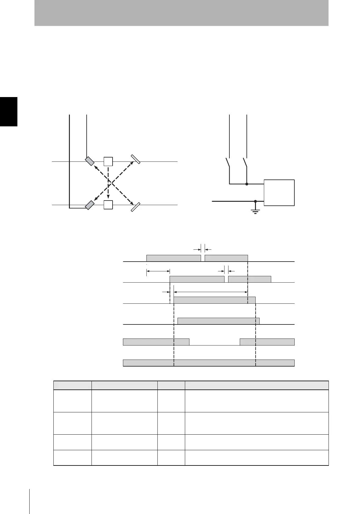
To enable the muting function, D1 and d1 must satisfy formulas (1) and (2), respectively.
This distance must prevent the muting function from being enabled by a person passing through the
muting sensors.
Also, install the F3SJ-B and muting sensors so that each workpiece passes through all muting sensors
before the next workpiece arrives at the first muting sensor.
<Wiring diagram>
<Timing chart>
Variable Variable name Value Description
T1min
Muting input time limit value
(minimum)
0.1 s
Minimum time difference between muting inputs 1 and 2.
If the time difference between muting inputs 1 and 2 is smaller
than this value, a muting error occurs.
T1max
Muting input time limit value
(maximum)
3 s
Maximum time difference between muting inputs 1 and 2.
If the time difference between muting inputs 1 and 2 is larger than
this value, a muting error occurs.
T2 Muting time limit 60 s
This is the muting function continuation time.
If muting state exceeds this time, the function is canceled.
T3
Maximum muting input pulse
duration
0.1 s
Maximum muting input time with allowable waveform cracks in
muting input 1 and 2.
B1A1
+24 VDC
0 V
Power
supply
Muting Input 2(Red)
Muting Input 1(White)
Muting Input 2 (Red)
Muting Input 1 (White)
Reflector
ReflectorA1
B1
F3SJ-B
Using a photoelectric switch as a muting sensor
* Two-wire type muting sensor cannot be used.
Using an N.O contact type switch as a muting sensor
A1, B1: Retro-reflective
photoelectric switch
- PNP Output
- ON when Interrupted
A1, B1: N.O. contact type switch
Muting sensor A1
ON
OFF
Muting sensor B1
Unblocked
Blocked
Safety output
ON
OFF
ON
OFF
Muting state
Enabled
Disabled
Auxiliary output
Blinking
OFF
T2 max.
1 Hz Blinking
F3SJ-B Unblocked
/Blocked
T3 max.
T3 max.
T1min to T1max
0.15 s max.