76
Chapter3 Mounting
F3SJ-E/B
User’s Manual
Wiring/Installation
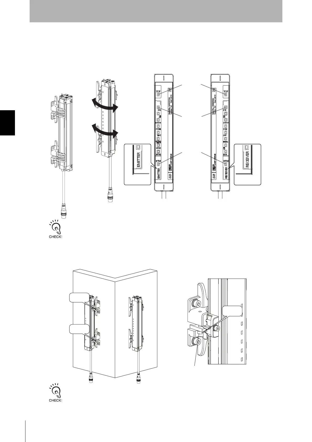
6. Turn ON the sensor to perform beam alignment.
Move the emitter from side to side (Figure 21) to align it to a center position where the stable-state
indicator (STB) is turned ON while checking the top beam state and bottom beam state with the top-
beam-state indicator (TOP) and bottom-beam-state indicator (BTM). (Figure 22)
Next, move the receiver from side to side (Figure 21) to align it to a center position where the stable-
state indicator (STB) is turned ON. (Figure 22)
- Confirm that there is no interrupting object in the detection zone before adjusting beams.
- If the stable-state indicator (STB) does not turn ON despite performing alignment, check if the mounting surfaces of
the emitter/receiver are parallel, and if the mounting height of the emitter/receiver is appropriate. Using optional
Laser Alignment Kit (F39-PTJ) makes alignment easier.
7. Tighten the lightly tightened the hexagon socket head cap screws (M3 x 18) of Intermediate Bracket (3)
to prevent rotation. (Figure 23)
If there are three or more Intermediate Brackets, tighten the hexagon socket head cap screws (M3 x
18) from the order of top, bottom and middle brackets with a tightening torque at 0.54 N•m
(recommended).
Tightening screws with a torque that considerably exceeds the recommended torque may cause failure.
Mounting is complete.
Emitter
Receiver
TOP indicator
(Blue)
STB indicator
(Green)
BTM indicator
(Blue)
EMITTER
RECEIVER
Tighten
securely
Enlarged view
Side mounting
Backside mounting
Tighten
securely
Tighten
securely
Hexagon socket head
cap screw (M3 x 18)