5 - 25
5 Setup and Wiring
Vision System FH/FZ5 series Hardware Setup Manual (Z366)
5-3 Sensor Controller Installation
5
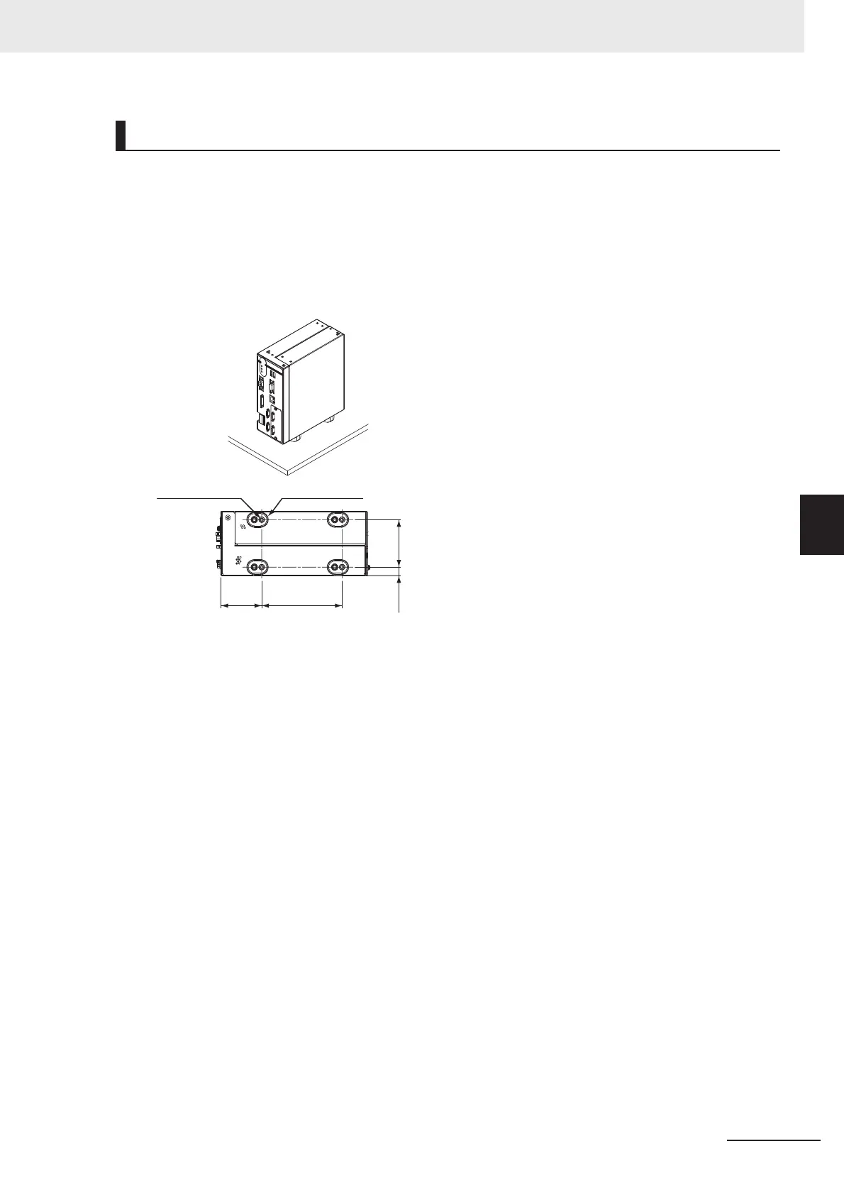
5-3-4 FZ5 Series
• Make sure to tighten all installation screws securely.
• Maintain a minimum clearance of 50 mm above the controller to improve air circulation.
A minimum clearance of 25 mm between other devices must also be maintained on the right, left and
back sides of product.
• Do not install the product immediately above significant heat sources, such as heaters, transformers,
or large-capacity resistors.
• Do not install the product in a cabinet containing high-voltage equipment.
• Do not install the Sensor Controller within 200 mm of power cables.
Note Fix without removing the insulation leg because neither the ventilation route is closed nor the case are con-
nected with FG.
Mounting of the FZ5-L Series
51
4-M4 depth 6.5
Insulation leg
100
5910.5

 Loading...


