6 I/O Interface
6 - 12
Vision System FH/FZ5 series Hardware Setup Manual (Z366)
Use the following parallel I/O cable.
XW2Z-S013-
*1. Cable is available in 2 m/5 m.
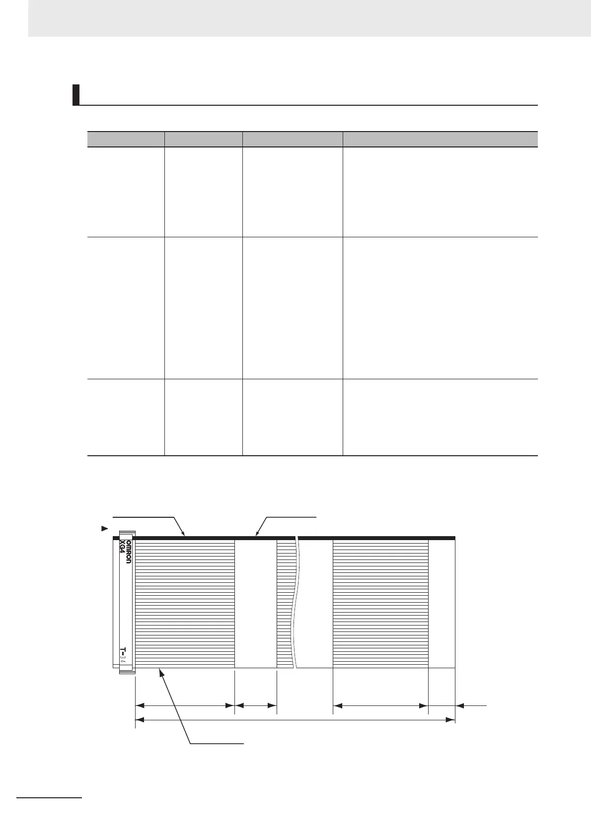
Cable. I/O connector and Terminal Block
Item Model Description Remark
Parallel I/O
Cable
XW2Z-S013- FH series only
Cable length: 2 m, 5 m
Minimum bending
radius: 10 mm
• 2 Cables are required for all I/O signals.
• This cable is the type of one side flat cable
and another side connector.
• Connect the parallel I/O cable with more than
the minimum bending radius.
• Insert the cables length into in the model
number as follows. 2 = 2 m, 5 = 5 m
Parallel I/O
Cable for Con-
nector-terminal
Conversion Unit
XW2Z-EE FH series only
Cable length: 0.5 m,
1 m, 1.5 m, 2 m, 3 m
5 m
Minimum bending
radius: 83.2 mm
• 2 Cables are required for all I/O signals.
• Connect the parallel I/O cable with more than
the minimum bending radius.
• Insert the cables length into in the model
number as follows.
050 = 0.5 m, 100 = 1 m, 150 = 1.5 m, 200 =
2 m, 300 = 3 m, 500 = 5 m
• Connector-Terminal Block Conversion Units
can be connected
(Terminal Blocks Recommended Products:
OMRON XW2R-34G-T)
Connector-Termi-
nal Block Con-
version Units,
General-purpose
devices
XW2R-34G-T • Insert the wiring into in the model number
as follows.
Phillips screw = J, Slotted screw (rise up) =
E, Push-in spring = P
Refer to the XW2R Series catalog (Cat. No.
G077) for details.
L
*1
1
2
33
34
(70) (70) (15)(30)
Unfused part
Cable mark
Fused part

 Loading...


