6 I/O Interface
6 - 16
Vision System FH/FZ5 series Hardware Setup Manual (Z366)
[Output]
Applicable signals/
• No. 15 to 19 pin:
Connect the COMOUT0 terminal when using these signals.
• No. 48, 49, 51 to 57 pins:
Connect the COMOUT2 terminal when using these signals.
• No.58 to 66 pins:
Connect the COMOUT3 terminal when using these signals.
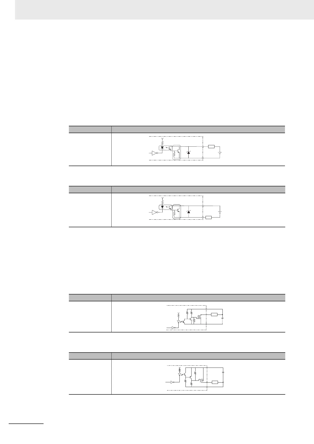
• Internal Specification for NPN Connection
• Internal Specification for PNP Connection
[Output]
Applicable signals/
• No.20 to 23 pins:
Connect the COMOUT1 and COMIN0 terminals when using these signals.
a) Internal Specification for NPN Connection
b) Internal Specification for NPN Connection
Item Specifications
Internal circuit
diagram
Item Specifications
Internal circuit
diagram
Item Specifications
Internal circuit
diagram
Item Specifications
Internal circuit
diagram
Each output terminal
Load
COM OUT
+
COM OUT
+
Each output terminal
Load
COM OUT
COM IN
+
Load
Each output
terminal
COM OUT
COM IN
+
Load
Each output
terminal

 Loading...


