6 - 15
6 I/O Interface
Vision System FH/FZ5 series Hardware Setup Manual (Z366)
6-1 Parallel Interface
6
6-1-3 FH-L Series
Parallel interface is NPN/PNP in common. An appropriate wiring is required according on the external
device.
[Input]
Applicable signals/
• No.37, 39 to 46 pin:
Connect the COMIN2 terminal when using these signals.
a) Internal Specification for NPN Connection
b) Internal Specification for PNP Connection
[Input]
Applicable signals/
• No.4 pin:
Connect the COMIN1 terminal when using these signals.
a) Internal Specification for NPN Connection
b) Internal Specification for PNP Connection
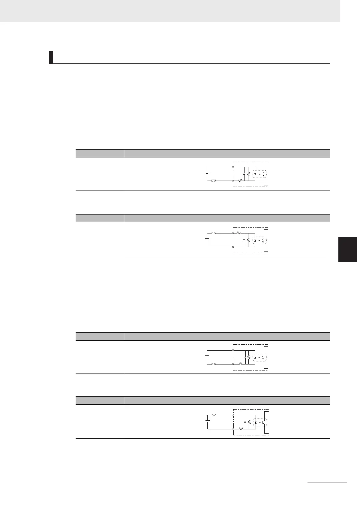
Internal Specifications for Parallel Interface
Item Specifications
Internal circuit
diagram
Item Specifications
Internal circuit
diagram
Item Specifications
Internal circuit
diagram
Item Specifications
Internal circuit
diagram
COM IN
+
Each input terminal
COM IN
+
Each input terminal
COM IN
+
Each input terminal
COM IN
+
Each input terminal

 Loading...


