6 I/O Interface
6 - 20
Vision System FH/FZ5 series Hardware Setup Manual (Z366)
Terminal assignments and signal names should be set according to the FH Sensor Controller's opera-
tion mode settings. Verify that the wiring conforms to that.
Additional Information
For Operation Mode, refer to the Setting the Operation Mode in Vision System FH/FZ5 Series
(Cat. No. Z365).
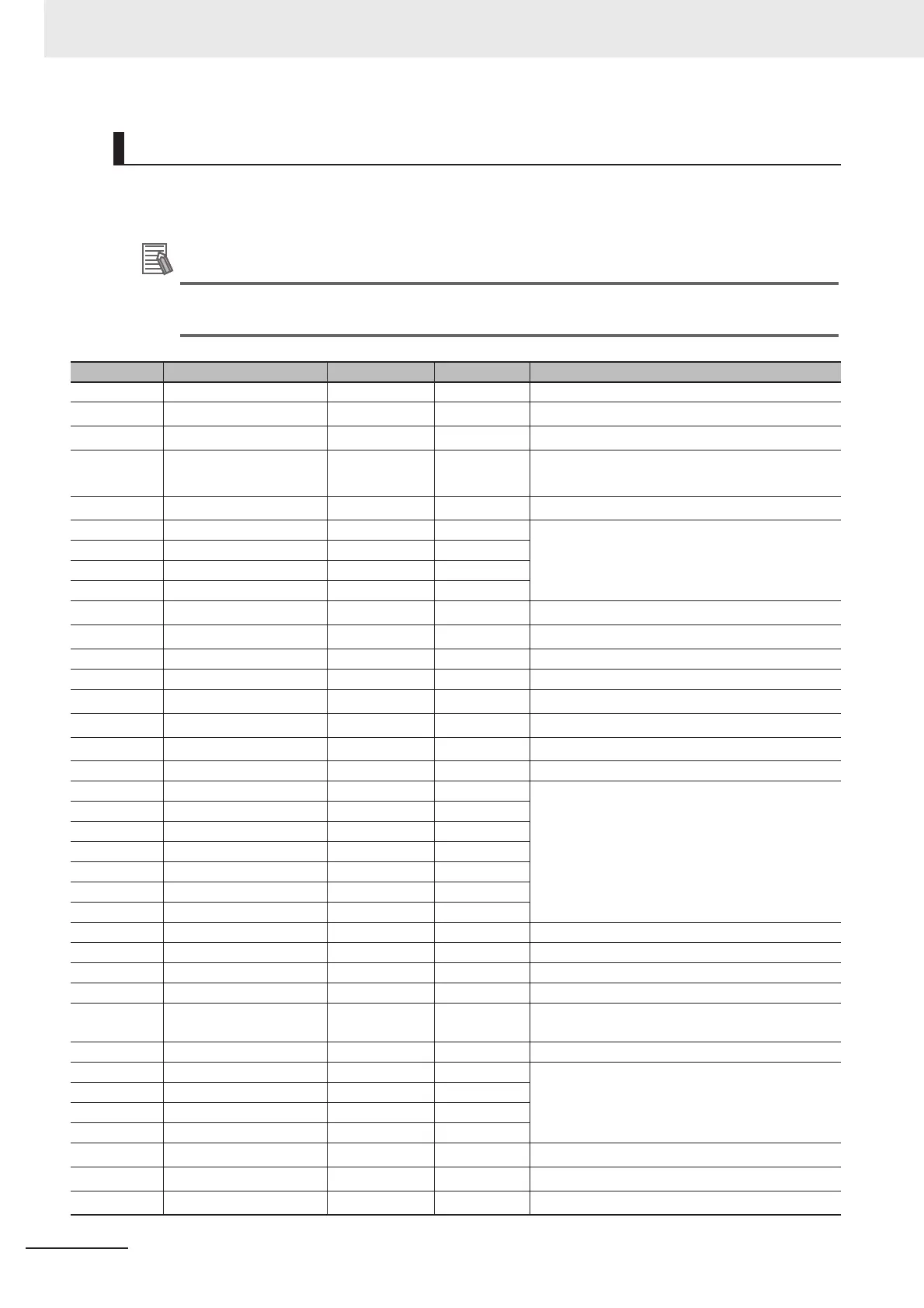
Pin Layout
No. Signal name Wire color Mark (red) Function
A1 COMIN Orange Ŷ Common for input signals
A2
ENCTRIG_A1
*2
Gray Ŷ Encoder trigger input (Phase A)
A3
ENCTRIG_B1
*2
White Ŷ Encoder trigger input (Phase B)
A4
STEP1
*2
/
ENCTRIG_Z1
*2
Yellow Ŷ Measurement trigger input/
Encoder trigger input (Phase Z)
A5
DSA1
*2
Pink Ŷ Data send request signal
A6 DI1 Orange ŶŶ Command inputs
A7 DI3 Gray ŶŶ
A8 DI5 White ŶŶ
A9 DI7 Yellow ŶŶ
A10 STGOUT1 Pink ŶŶ
Strobe trigger output
*1
A11 STGOUT3 Orange ŶŶŶ
Strobe trigger output
*1
A12 ERROR Gray ŶŶŶ ON when there is an error.
A13 COMOUT1 White ŶŶŶ Common for output signals
A14
GATE1
*2
Yellow ŶŶŶ ON for the set output time
A15
OR1
*2
Pink ŶŶŶ Overall judgment result
A16
READY1
*2
Orange ŶŶŶŶ ON when image input is allowed
A17 COMOUT2 Gray ŶŶŶŶ Common for output signals
A18 DO1 White ŶŶŶŶ Data output
A19 DO3 Yellow ŶŶŶŶ
A20 DO5 Pink ŶŶŶŶ
A21 DO7 Orange
ŶŶŶŶŶŶŶŶŶŶŶŶŶŶŶŶŶŶŶŶŶŶŶŶŶŶŶŶŶŶŶŶŶŶŶŶŶŶŶŶ
A22 DO9 Gray
ŶŶŶŶŶŶŶŶŶŶŶŶŶŶŶŶŶŶŶŶŶŶŶŶŶŶŶŶŶŶŶŶŶŶŶŶŶŶŶŶ
A23 DO11 White
ŶŶŶŶŶŶŶŶŶŶŶŶŶŶŶŶŶŶŶŶŶŶŶŶŶŶŶŶŶŶŶŶŶŶŶŶŶŶŶŶ
A24 DO13 Yellow
ŶŶŶŶŶŶŶŶŶŶŶŶŶŶŶŶŶŶŶŶŶŶŶŶŶŶŶŶŶŶŶŶŶŶŶŶŶŶŶŶ
A25 COMOUT3 Pink
ŶŶŶŶŶŶŶŶŶŶŶŶŶŶŶŶŶŶŶŶŶŶŶŶŶŶŶŶŶŶŶŶŶŶŶŶŶŶŶŶ
Common for output signals
B1 RESET Orange Ŷ Controller restart
B2 ENCTRIG_A0 Gray Ŷ Encoder trigger input (Phase A)
B3 ENCTRIG_B0 White Ŷ Encoder trigger input (Phase B)
B4 STEP0/ENCTRIG_Z0 Yellow Ŷ Measurement trigger input/
Encoder trigger input (Phase Z)
B5 DSA0 Pink Ŷ Data send request signal
B6 DI0 Orange ŶŶ Command inputs
B7 DI2 Gray ŶŶ
B8 DI4 White ŶŶ
B9 DI6 Yellow ŶŶ
B10 STGOUT0 Pink ŶŶ
Strobe trigger output
*1
B11 STGOUT2 Orange ŶŶŶ
Strobe trigger output
*1
B12
RUN/BUSY1
*2
Gray ŶŶŶ
*3

 Loading...


