6 I/O Interface
6 - 34
Vision System FH/FZ5 series Hardware Setup Manual (Z366)
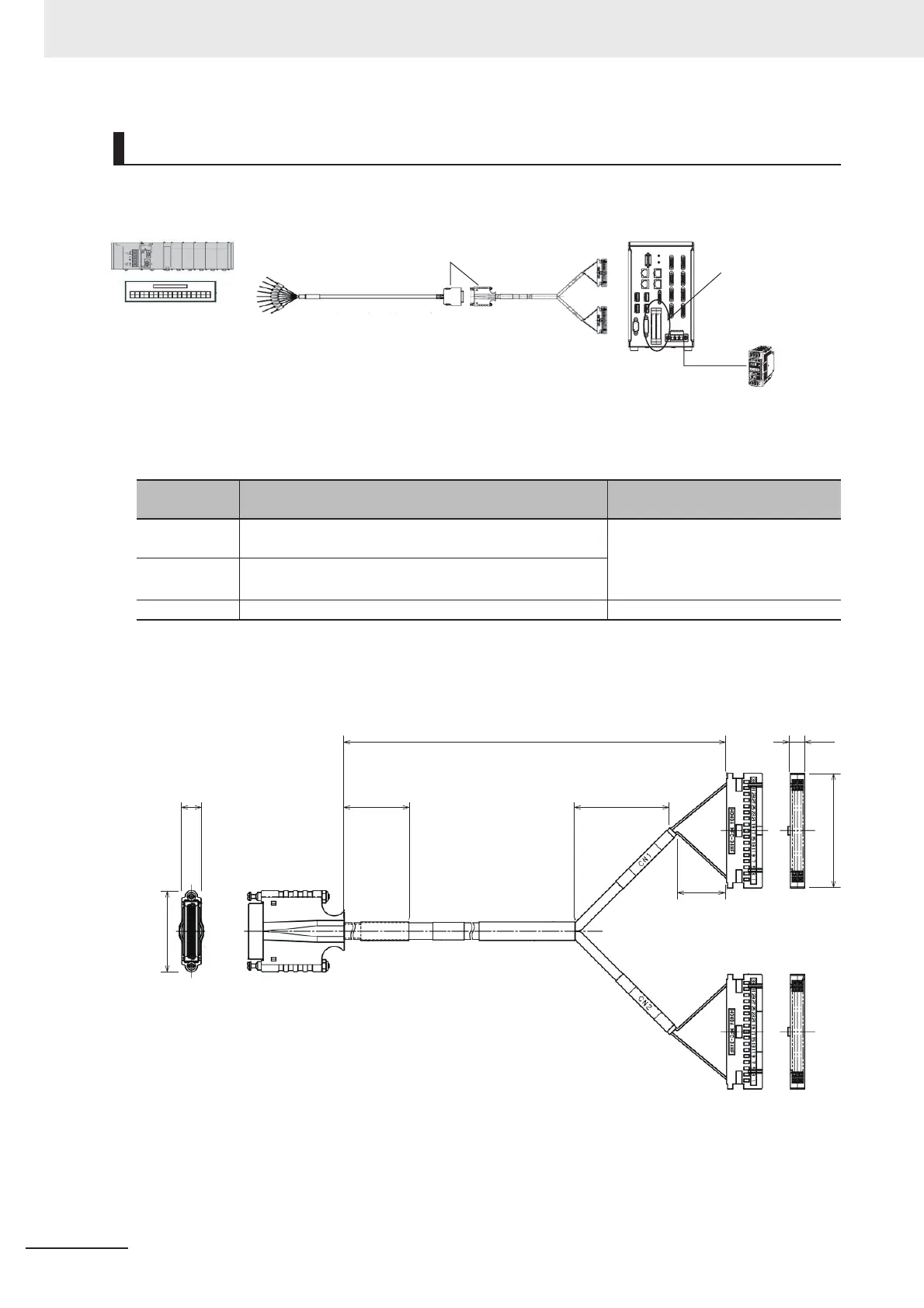
Connection Structure
Cable (FH-VPX-FZ)
FH-VPX-FZ
Connector
No.
Connection Destination Special Notes
CN1 Connect to the parallel port CN1 of the FH Sensor Con-
troller.
Even if you connect the revers CN1
and CN2, Sensor Controller does
not perform.
It is immune to breakdown.
CN2 Connect to the parallel port CN2 of the FH Sensor Con-
troller.
CN3 Connect to the Parallel I/O cable FZ-VP.
PLC, terminal blocks or
other products
FZ-VP / FZ-VPX
CN3
CN1
CN2
FH-VPX-FZ
Power supply used
in the FH controller:
Power supply S8VS
series (24 VDC)
Parallel connector
(CN1/CN2)
FH controller
Connecting the FZ-VP and the FH-VPX-
* After the connection, lock it securely.
CN3
CN1
CN2
8
34
40
500
(35)
(20)
7
(Unit: mm)
47.8

 Loading...


