6 I/O Interface
6 - 36
Vision System FH/FZ5 series Hardware Setup Manual (Z366)
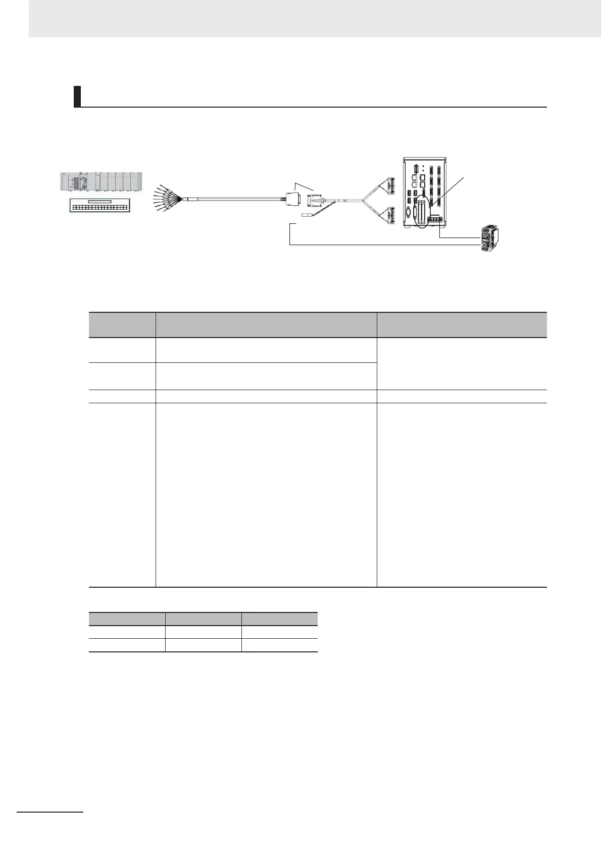
Connection Structure
*1. COM terminal polarity of NPN/PNP
FH-VPX-FZL
Connector
No.
Connection Destination Special Notes
CN1 Connect to the parallel port CN1 of the FH Sensor
Controller.
Even if you connect the revers CN1 and
CN2, Sensor Controller does not per-
form.
It is immune to breakdown.
CN2 Connect to the parallel port CN2 of the FH Sensor
Controller.
CN3 Connect to the Parallel I/O cable FZ-VP.---
CN4 Connect to 24 V power source depending on the
PN/PNP polarity as below table.
Connect to the Parallel I/O cable
FZ-VP.
• When power source and DI0 are
non-isolated and no problem:
Possible to connect the power source
same as FH series.
• When you want to isolate the power
source and DI0:
Disposable to use the power source of
FH series.
Connect the other power source to
CN4.
Recommendation: S8VS series
DC24V.
NPN PNP
COMIN +V -V
COMOUT -V +V
Parallel connector
(CN1/CN2)
FH controller
Connecting the FZ-VP and the FH-VPX-
* After the connection, lock it securely.
CN3
CN4
CN1
CN2
PLC, terminal blocks or
other products
FH-VPX-FZL
FZ-VP / FZ-VPX
Power supply used
in the FH controller:
Power supply S8VS
series (24 VDC)

 Loading...


