EasyManuals Logo

Omron fh series Hardware Manual

Omron fh series
254 pages
To Next Page IconTo Next Page
To Previous Page IconTo Previous Page
Page #68 background imageLoading...
Page #68 background image
3 Configuration
3 - 10
Vision System FH/FZ5 series Hardware Setup Manual (Z366)
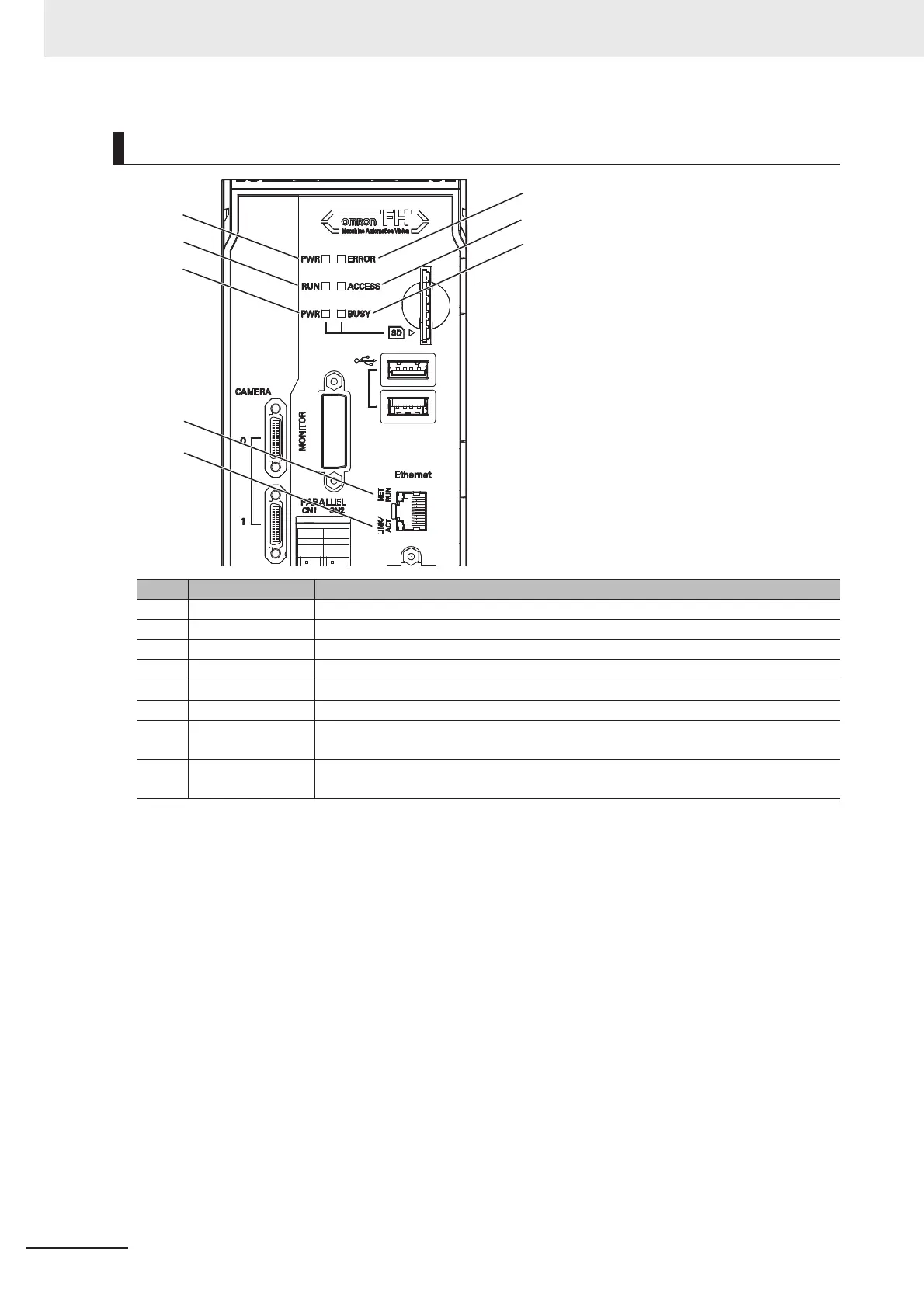
Component Names and Functions
LED name Description
(A) PWR LED Lit while power is ON.
(B) ERROR LED Lit when an error has occurred.
(C) RUN LED Lit while the layout turned on output setting is displayed.
(D) ACCESS LED Blinks while the internal nonvolatile memory is accessed.
(E) SD PWR LED Lit while power is supplied to the SD memory card and the card is usable.
(F) SD BUSY LED Lit when access to the SD memory card.
(G) Ethernet NET
RUN LED
Lit while Ethernet communications are usable.
(H) Ethernet NET
LINK/ACT LED
Blinks when connected with an Ethernet device, and blinks while performing com-
munications.
(A)
(C)
(E)
(B)
(D)
(F)
(G)
(H)

Table of Contents

Other manuals for Omron fh series

Questions and Answers:

Question and Answer IconNeed help?

Do you have a question about the Omron fh series and is the answer not in the manual?

Omron fh series Specifications

General IconGeneral
TypeMachine Vision System
SeriesFH Series
Power Supply24 VDC
Storage Temperature-20 to 60°C
Humidity35 to 85% RH (non-condensing)
Image SensorCMOS
Processing SpeedHigh-speed processing
ConnectivityEthernet
I/ODigital I/O
Operating SystemEmbedded OS
I/O PortsEthernet, USB

Related product manuals