3 - 11
3 Configuration
Vision System FH/FZ5 series Hardware Setup Manual (Z366)
3-1 Sensor Controller
3
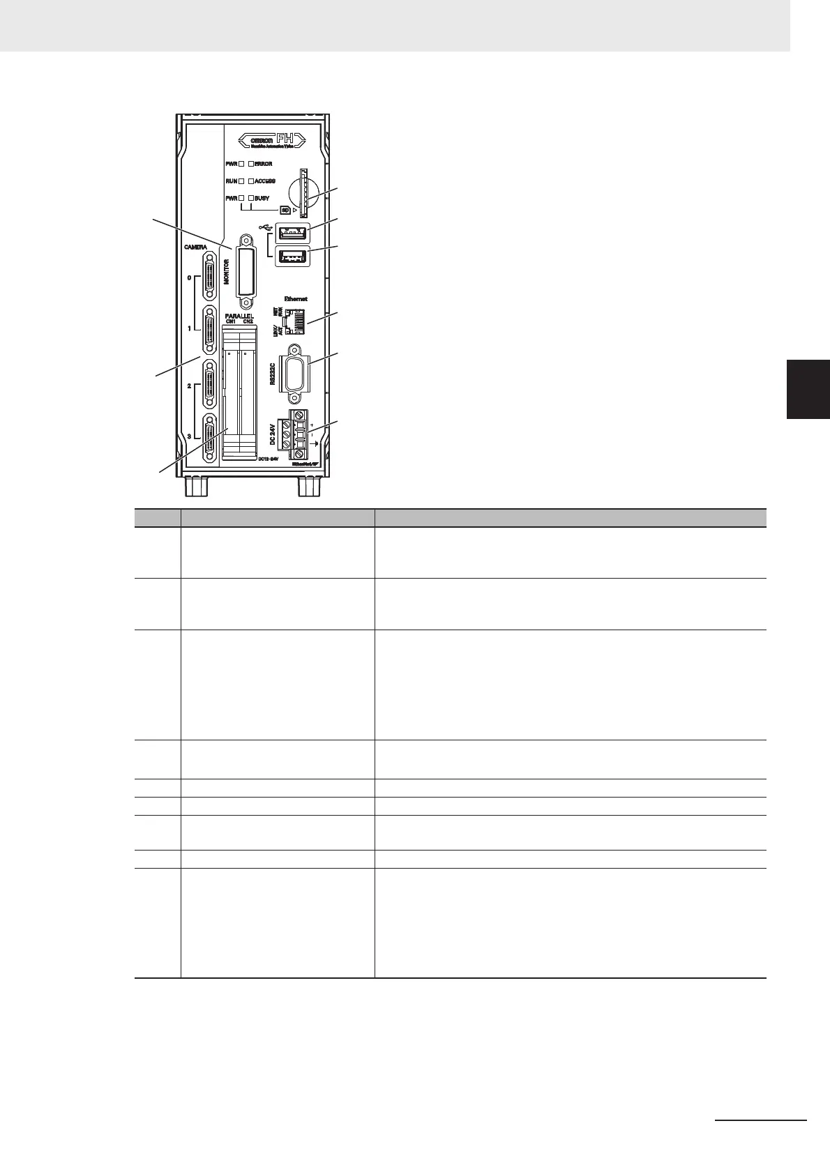
3-1-2 FH-L Series
Connector name Description
(A) SD memory card installation
connector
Install the SD memory card. Do not plug or unplug the SD memory
card during measurement operation. Otherwise measurement time
may be affected or data may be destroyed.
(B) USB 2.0 connector Connects to USB 2.0. Do not insert or remove during loading or
writing of measurement or data. The measurement time can be
longer or data can be damaged.
(C) USB 3.0 connector Connects to USB 3.0. Do not insert or remove during loading or
writing of measurement or data. The measurement time can be
longer or data can be damaged.
USB 3.0 has a high ability to supply the bus power.
Use the Sensor Controller by combining USB 3.0, faster transport
can be realized.
(D) Ethernet connector Connect an Ethernet device.
Shared Ethernet port and EtherNet/IP port.
(E) RS-232C connector Connect an external device such as a programmable controller
(F) Monitor connector Connect a monitor.
(G) Parallel connector
(control lines, data lines)
Connect the controller to external devices such as a sync sensor.
(H) Camera connector Connect a camera.
(I) Power supply terminal connector Connect a DC power supply. Wire the controller independently on
other devices. Wire the ground line. Be sure to ground the FH Sensor
Controller alone.
Use the attachment power terminal connector (male) of FH-XCN-L
series.
For details, refer to 5-3 Sensor Controller Installation in this manual.
(F)
(G)
(H)
(D)
(E)
(I)
(A)
(C)
(B)

 Loading...


