3 - 21
3 Configuration
Vision System FH/FZ5 series Hardware Setup Manual (Z366)
3-1 Sensor Controller
3
3-1-4 FZ5-L Series
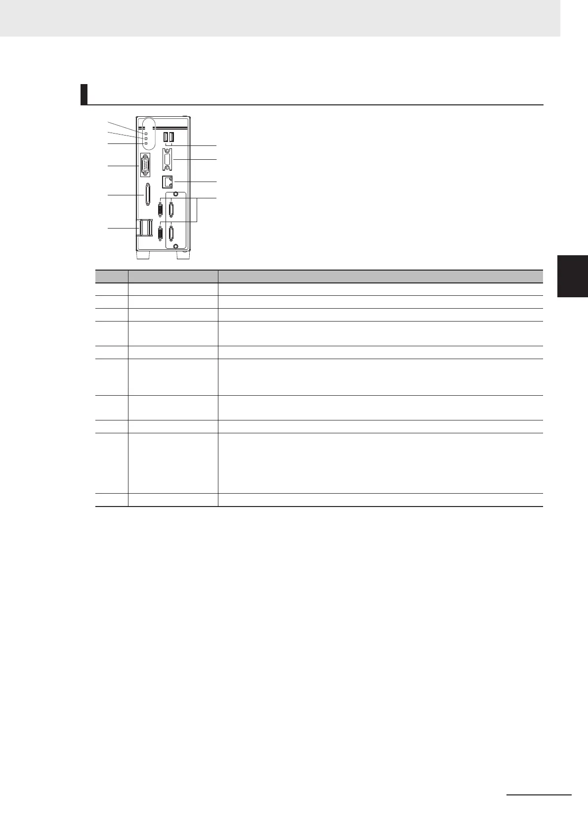
Component Names and Functions
Connector name Description
(1) POWER LED Lit while power is ON.
(2) RUN LED Lit while the layout turned on output setting is displayed.
(3) ERROR LED Lit when an error has occurred.
(4) I/O connector (con-
trol lines, data lines)
Connect the controller to external devices such as a sync sensor.
(5) Camera connector Connect cameras.
(6) Power Connect a DC power supply.
Wire the power supply unit independently of other devices.
After wiring, replace the terminal cover.
(7) Monitor connector
(analog RGB)
Connect a monitor.
(8) RS-232C connector Connect an external device such as a personal computer.
(9) USB connector Connect a track ball, mouse and USB memory. A total of four USB ports are pro-
vided and any of them can be used.
However, when connecting two USB memories, do not connect them to adjacent
ports. Doing so may cause the USB memories to come into contact, resulting in
malfunction or damage.
(10) Ethernet connector Connect the controller to a computer.
(1)
(9)
(7)
(10)
(5)
(8)
(6)
(4)
(2)
(3)

 Loading...


