l
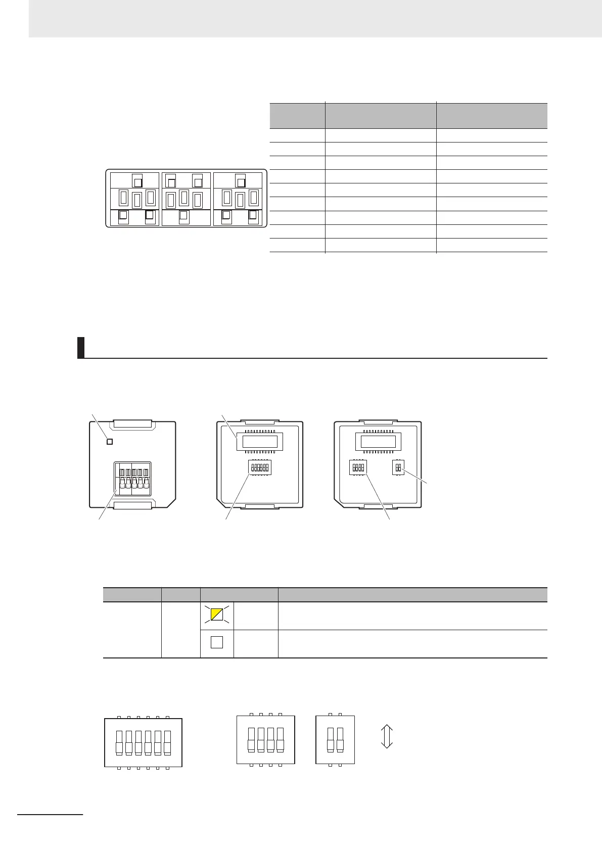
RS-232C Terminal Block
Abbrevia-
tion
Signal name I/O
SG0 RD SD ER
SG1
DR RS CS
SHLD
SG0 Signal grounding ---
RD Receive data Input
SD Send data Output
ER Data terminal ready Output
SG1 Signal grounding ---
DR Data set ready Input
RS Send request Output
CS Data can be sent Input
SHLD Shield ---
As the Option Board does not have a 5 V power supply terminal, it cannot be connected to external
converters such as an CJ1W-CIF11 and NT-AL001, or an NV3W-M£20L Programmable Terminal.
The terminal block is not removable.
RS-422A/485 Option Board (NX1W-CIF11/NX1W-CIF12)
RS-422A/485 terminal
block
Operation setting DIP
switch (SW1)
Operation setting DIP
switch (SW1)
Operation setting DIP
switch (SW2)
Communications
status indicator
CPU Unit connector
Front
Back (CIF11) Back (CIF12)
SW 1
1
2
3
4
5
6
O
N
1
2
3
4
O
N
1
2
O
N
SW 1 SW 2
COMM
RDA- RDB+ SDA- SDB+ SHLD
l
Communications Status Indicator
Indicator Color Status Description
COMM Yellow Lit. Communications are being performed.
Not lit. Communications are not performed.
l
Operation Setting DIP Switch
CIF11
CIF12
1
2
3
4
5
6
O
N
1
2
3
4
O
N
1
2
O
N
SW1SW1 SW2
OFF ON
3 Configuration Units
3-24
NX-series NX1P2 CPU Unit Hardware User’s Manual (W578)

 Loading...


