CIF11 CIF12
Setting
SW No. SW No.
SW1 1 SW1 1 ON Terminating re-
sistance provid-
ed
Select whether a terminating resistance is
provided or not. The value of a terminating
resistance is approximately 220 Ω.
OFF
Terminating re-
sistance not pro-
vided
2 2 ON Two-wire type Select the two-wire or four-wire type.
To set the two-wire type, turn ON both No. 2
and No. 3 pins. T
o set the four-wire type,
turn OFF both No. 2 and No. 3 pins.
OFF Four-wire type
3 3 ON Two-wire type
OFF Four-wire type
4 4 --- --- Not used.
5 SW2 1 ON RS control ena-
bled
Select whether to enable the RS control for
receive data.
T
o prohibit the echo back, enable the RS
control (ON).
OFF RS control disa-
bled
(continuous re-
ception)
6 2 ON RS control ena-
bled
Select whether to enable the RS control for
send data.
For a four-wire, 1-to-N connection, enable
the RS control (ON) if you connect the Unit
to a device on the N side.
For a two-wire connection, always enable
the RS control (ON).
OFF RS control disa-
bled
(continuous
transmission)
All pins are turned OFF by default.
Use a narrow-tipped tool such as a flat-blade screwdriver to change the settings of the DIP
switches.
l
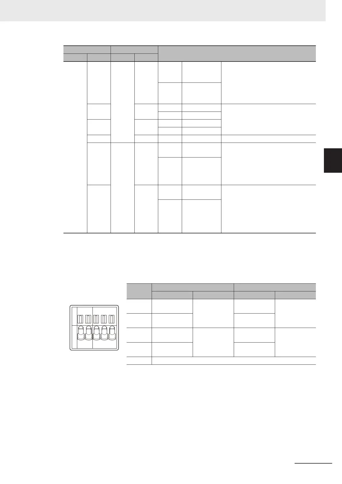
RS-422A/485 Terminal Block
Abbrevi-
ation
Four-wire type selected Two-wire type selected
Signal name I/O Signal name I/O
RDA- Reception data − Input Communication
data −
I/O
*1
RDB+ Reception data + Communication
data +
SDA- Transmission da-
ta −
Output Communication
data −
I/O
*1
SDB+ Transmission da-
ta +
Communication
data +
SHLD Shield
*1. For two-wire connection, either the RDA-/RDB+ pair or SDA-/SDB+ pair can be used.
3 Configuration Units
3-25
NX-series NX1P2 CPU Unit Hardware User’s Manual (W578)
3-3 Serial Communications Option Board
3
3-3-3 Part Names and Functions
 Loading...


