EasyManuals Logo

Omron NX1P2 series Hardware User Manual

Omron NX1P2 series
264 pages
To Next Page IconTo Next Page
To Previous Page IconTo Previous Page
Page #184 background imageLoading...
Page #184 background image
l
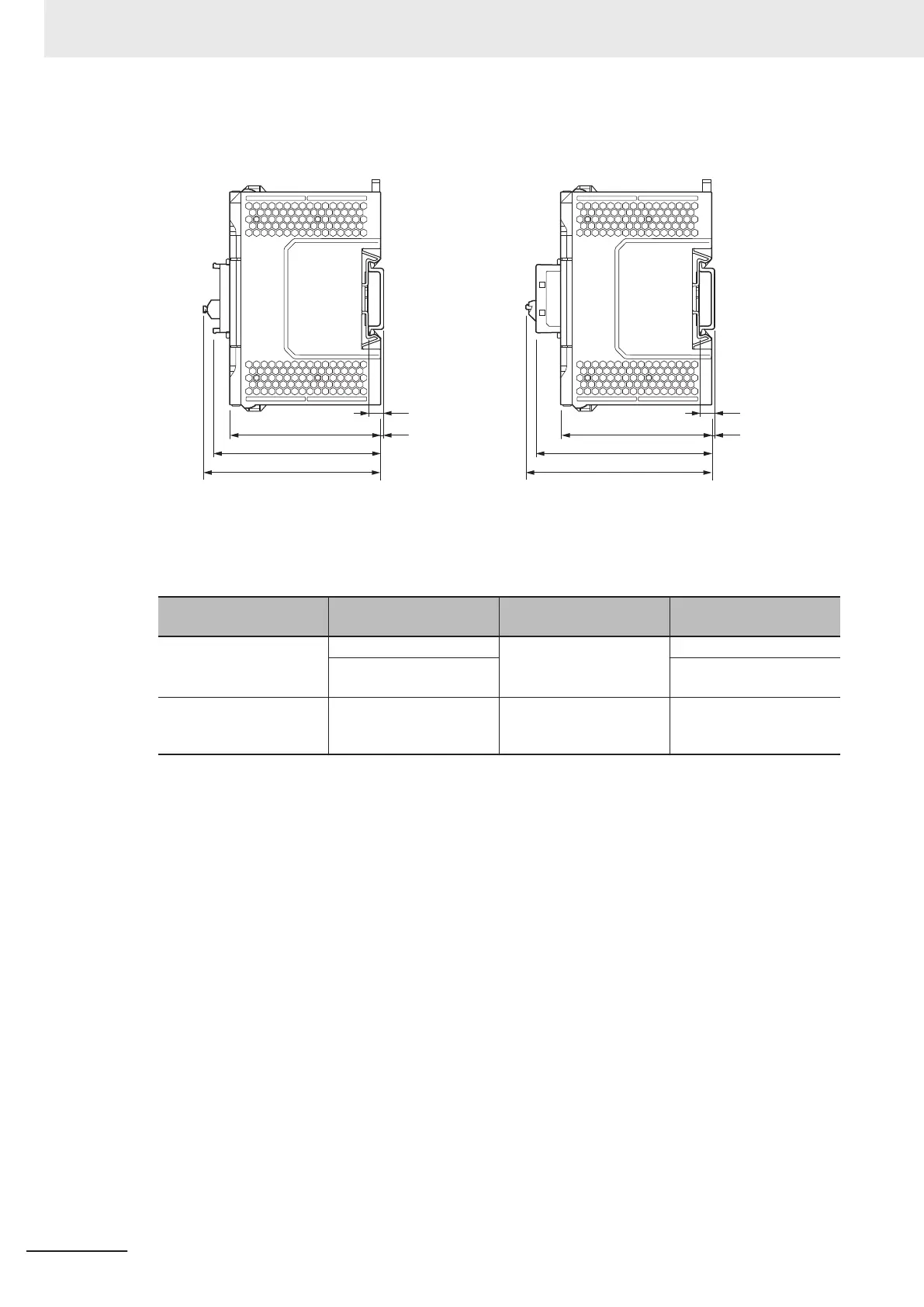
Depth When Option Board Is Attached
Serial Communications Option Board attached Analog I/O Option Board attached
71
(D)
(E)
(B) (B)
(A)
71
(D)
(E)
(A)
Unit: [mm]
The overall depth when an Option Board is attached is as follows.
(A) and (B) in the figure are the same as the DIN Track dimension and the dimension from the back
of the Unit to the back of the DIN T
rack shown in the previous page, respectively.
Unit name Model Depth to Option Board (D)
Depth to the end of the
terminal block (E)
Serial Communications Op-
tion Board
NX1W-CIF01 72.5 mm 77.8 mm
NX1W-CIF11
NX1W
-CIF12
74.6 mm
Analog I/O Option Board
NX1W-ADB21
NX1W-DAB21V
NX1W
-MAB221
83.7 mm 89.1 mm
5 Installation and Wiring
5-40
NX-series NX1P2 CPU Unit Hardware Users Manual (W578)

Table of Contents

Other manuals for Omron NX1P2 series

Questions and Answers:

Question and Answer IconNeed help?

Do you have a question about the Omron NX1P2 series and is the answer not in the manual?

Omron NX1P2 series Specifications

General IconGeneral
ModelNX1P2 Series
ManufacturerOmron
TypeController
CPU Units1
Program Capacity5 MB
Data Memory Capacity128 KB
Ethernet Ports1
Serial Ports1
Built-in EtherNet/IP PortYes
Built-in EtherCAT PortYes
Built-in USB PortYes
SD Memory Card SlotYes
USB Port1
Power Supply Voltage24 VDC
Programming LanguageLadder, Structured Text, Function Block Diagram
Communication ProtocolsEtherNet/IP, EtherCAT, Serial (RS-232C)

Related product manuals