Wiring for Analog Inputs and Outputs
To prevent noise, 2-core shielded twisted-pair cable (AWG20 to AWG26) should be used.
l
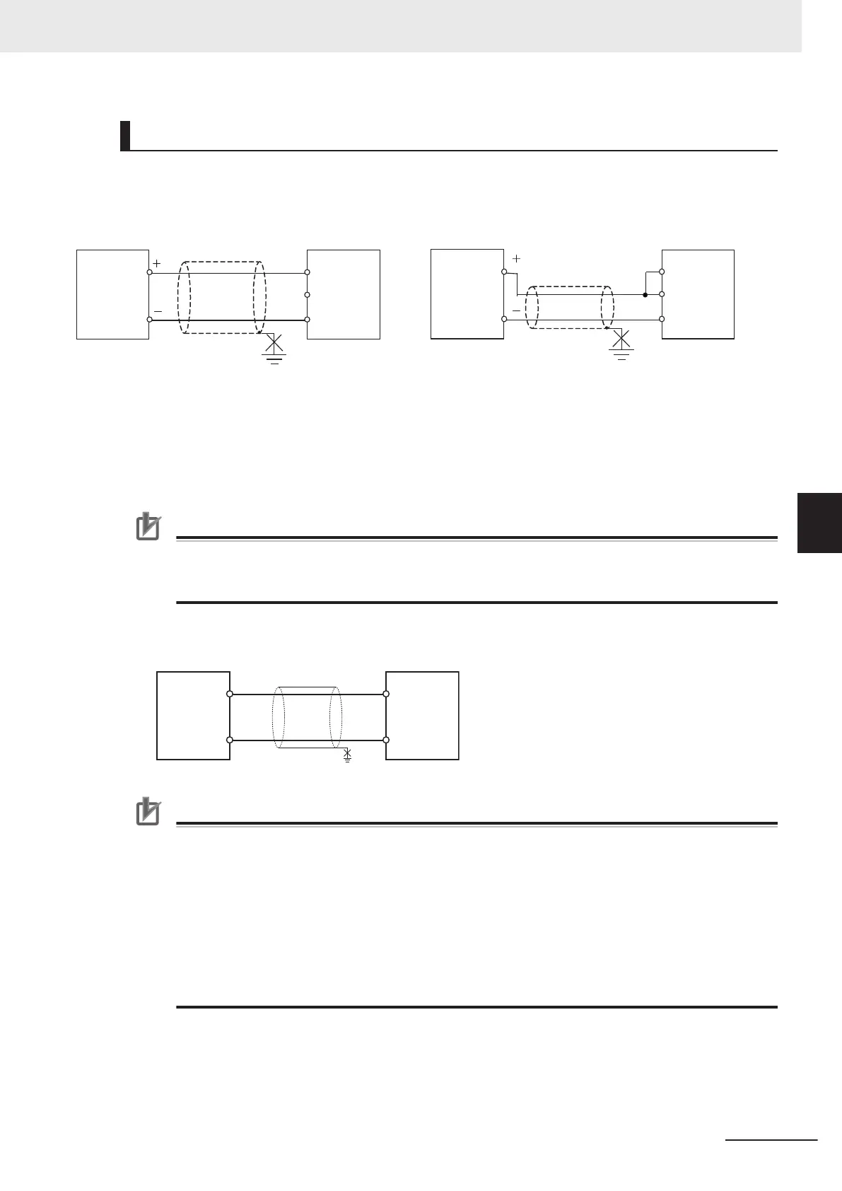
Wiring for Analog Inputs
Analog
output
device with
voltage
output
Analog
Input
Option
Board
VI VI
COM
I I
Analog
output
device with
current
output
Analog
Input
Option
Board
COM
I I
2-core shielded
twisted-pair cable
2-core shielded
twisted-pair cable
FG
FG
* When using current input, short-circuit the VI
terminal (voltage input) and the II terminal
(current input) of the Analog Input Option Board.
*
Voltage input Current input
However, if noise affects the Unit, ground the end of the shield on the Input Unit side.
You can use the NX-TBX01 Shield Connection Unit to ground more than one shield.
Precautions for Correct Use
• When you do not use some inputs, be sure to short-circuit the VI input terminals with the
COM terminal.
• Separate the lines from power lines (e.g., AC power supply lines or power lines).
l
Wiring for Analog Outputs
COM
V OUT
Analog
Output
Option
Board
Analog
input
device with
voltage
input
FG
2-core shielded
twisted-pair cable
+
-
Precautions for Correct Use
To ensure this Option Board is kept in the best operating condition, observe the following points
when wiring to avoid the effects of the noise.
•
Use a shield wire (2 conductors, twisted wire) or a shield wire (3 conductors) as the input
connection line for each output. Connect the shield according to the specifications of the input
device.
• Wire the output connection lines and power lines (e.g., AC power supply lines or power lines)
separately. Do not place such lines in the same duct.
• Insert a noise filter into the power supply input section if noise comes from power supply lines
when using the same power supply to power an electrical welder or an electric discharge ma-
chine, or there is a high-frequency source nearby.
5 Installation and Wiring
5-81
NX-series NX1P2 CPU Unit Hardware User’s Manual (W578)
5-4 Wiring
5
5-4-12 Wiring the Analog I/O Option Board
 Loading...


