3-11
3-1 Servo Drive Specifications
3
Specifications
Function: Internally Set Speed Selection 1
Pin 6 is the Internally Set Speed Selection 1 Input (VSEL1) in Internal Speed Control Mode (when
Pn02 is set to 1).
Four speeds can be selected by using pin 6 in combination with the Internally Set Speed Selection
2 Input (VSEL2).
Reverse Drive Prohibit/Forward Drive Prohibit Input
Pin 7: Reverse Drive Prohibit Input (NOT)
Pin 8: Forward Drive Prohibit Input (POT)
Functions
These inputs prohibit forward and reverse operation (overtravel).
When an input is ON, operation is possible in that direction.
These inputs can be disabled using the setting of Drive Prohibit Input Selection (Pn04).
The motor will stop according to the setting of the Stop Selection for Drive Prohibition Input (Pn66).
Reverse Pulse/Forward Pulse, Feed Pulse/Direction Signal, 90° Phase Difference
Signal (Phase A/Phase B)
Pin 22: +Reverse Pulse (+CW), +Feed Pulse (+PULS), or +Phase A (+FA)
Pin 23: −Reverse Pulse (−CW), −Feed Pulse (−PULS), or −Phase A (−FA)
Pin 24: +Forward Pulse (+CCW), +Direction Signal (+SIGN), or +Phase B (+FB)
Pin 25: −Forward Pulse (−CCW), −Direction Signal (−SIGN), or −Phase B (−FB)
Functions
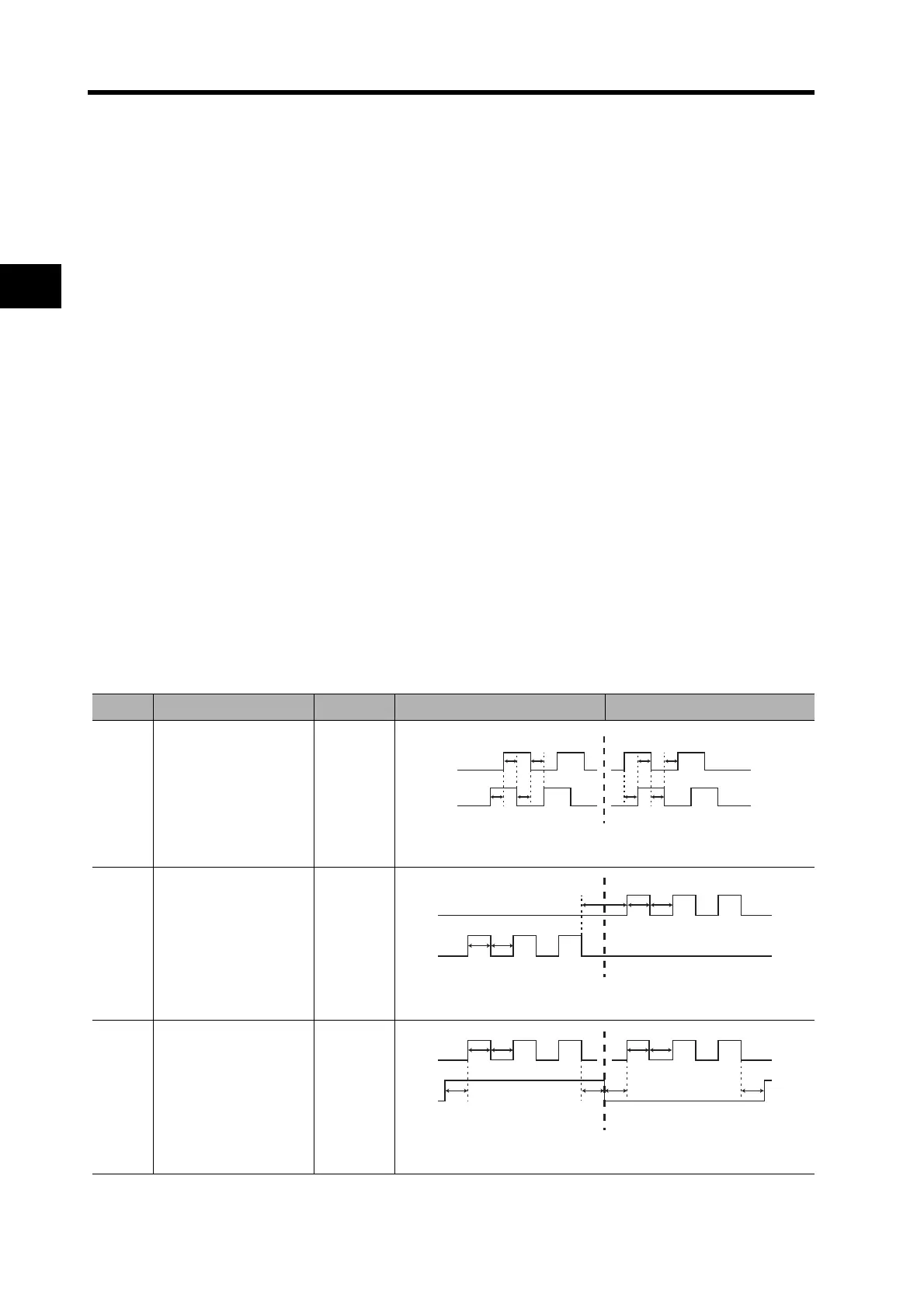
The functions of these signals depend on the setting of the Command Pulse Mode (Pn42).
If the photocoupler LED is turned ON, each signal will go high as shown above.
Setting Command pulse mode Input pins Servomotor forward command Servomotor reverse command
0 or 2
90° phase difference
signals
22: +FA
23: −FA
24: +FB
25: −FB
Line driver: t1 ≥ 2 µs
Open collector: t1 ≥ 5 µs
1
Reverse pulse/forward
pulse
22: +CW
23: −CW
24: +CCW
25: −CCW
Line driver: t2 ≥ 1 µs
Open collector: t2 ≥ 2.5 µs
3
Feed pulse/direction
signal
22: +PULS
23: PULS
24: SIGN
25: −SIGN
Line driver: t2 ≥ 1 µs
Open collector: t2 ≥ 2.5 µs
t1 t1 t1 t1
t1 t1t1 t1
Phase A
Phase B
t2 t2
t2
t2
t2
Low
Low
t2
High
Low
t2t2
t2 t2 t2 t2
t2