86
Configuration of Function Blocks Section 3-1
Field Input/Output blocks
Note Conventions Used in Describing ITEMs
Refer to the Function Block Reference Manual.
The Function Block Reference Manual defines reading and writing methods
according to the following four methods as one of R: Read, W: Write, or R/W:
R/W-enabled.
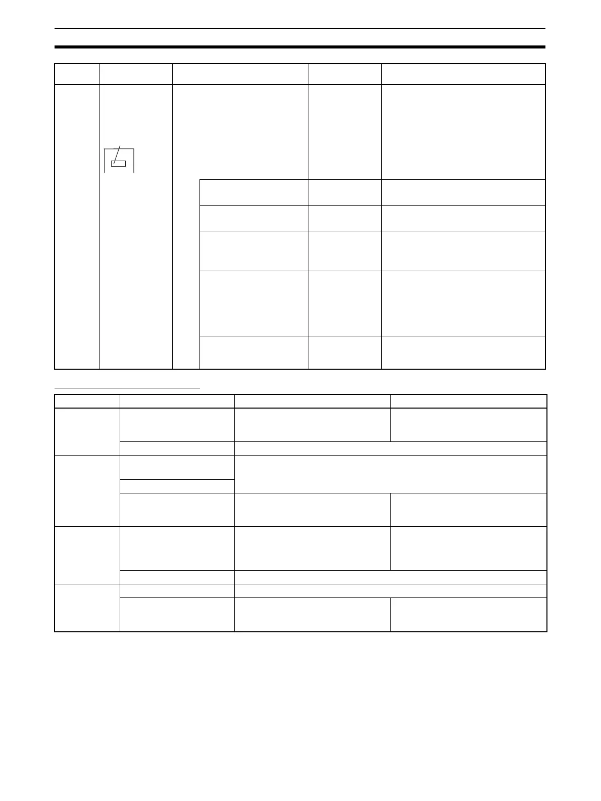
Parameter Basically, no sym-
bol in block dia-
gram (expressed
as follows in some
cases as an expla-
nation)
This is internal data upon which nei-
ther the above-described analog
input/output nor contact input/output
operations are performed.
There are two types of parameters:
parameters whose value can be
changed by one or a combination of
the methods 1) to 4) below, and
parameters whose value cannot be
changed by any of the following
methods (only indicated) in 5) below.
1) Parameter value can be
changed by CX-Process Tool
High alarm setting
(ITEM009) of the
Basic PID block
Set in CX-Process Tool.
2) Parameter value can be
changed using SCADA software.
Local Set Point set-
ting (ITEM023) of the
Basic PID block
Set in SCADA software.
3) Parameter value can be
changed by the Constant ITEM
Setting block (Block Model 171)
or the Variable ITEM Setting
block (Block Model 172).
Proportional band
setting (ITEM054) of
the Basic PID block
Constants or variables (analog signals) are written
according to the write destination of the Constant
ITEM Setting block (block number 171) or the Vari-
able ITEM Setting block (block number 172).
4) Parameter value can be
changed by the
Sequence
Table block (Block Model
302) or
Step Ladder Program
block (Block Model 301) or the
Contact Distributor block (Block
Model 201).
Auto/Manual switch
(ITEM086) of the
Basic PID block
This data is set according to the Sequence Table
block (Block Model 302) or Step Ladder Pro-
gram block (block number 301) or the Contact Dis-
tributor block (block number 201).
Note: Only “parameters” that are also “contact
inputs” (ITEMs whose ITEM type is specified as
“contact input/parameters” in the Function Block
Reference Manual)
5) Indication only (by Step Lad-
der Program)
PV execution error
indication (ITEM019)
of the Basic PID
block
Cannot be set
Function ITEM type Description Setting method
External ana-
log input
Specification of external
analog input
Analog signals are received from the
Analog Input Unit having the speci-
fied unit number.
Specify the unit number of the Analog
Input Unit.
Analog output Same as regular analog output ITEM
External ana-
log
output
Analog input connection
information
Same as regular analog input ITEM
Analog input
Specification of external
analog output
Analog signals are sent to the Analog
Output Unit having the specified unit
number.
Specify the unit number of the Analog
Output Unit.
External con-
tact input
Specification of external
contact input
Contact signals are received from the
Contact Input Unit allocated to the
leading specified CIO (channel I/O)
Area.
Specify the leading CIO (channel I/O)
Area allocated to the Contact Input
Unit.
Contact output Same as regular contact output ITEM
External con-
tact
output
Contact input Same as regular contact input ITEM
Specification of external
contact output
Specify the leading CIO (channel I/O)
Area allocated to the Contact Output
Unit.
Contact signals are sent to the Basic
I/O Unit allocated to the leading spec-
ified CIO (channel I/O) Area.
ITEM type Block diagram
symbol
Description Example Setting method
×××
ITEM numbe