129
Description of Operation Section 3-2
3-2-16 Order of Operations
The order of execution for all of the functions block that are to be executed in
the same cycle is, first of all, determined by execution groups set by the sys-
tem. Within these groups, the order of execution is determined either by the
block addresses or, for control and operation blocks, by user settings or the
arrangement of the blocks in the block diagram.
The groups set by the system are as follows (in order from 1 to 4):
1,2,3... 1. Input user link table blocks (including the Di and Ai field input terminals cre-
ated as virtual blocks on the CX-Process Tool)
2. System Common block
3. Control, Operation, External Controller, Sequence Table, and Step Ladder
blocks
The order of execution for control, operation, external controller, sequence
table, and step ladder blocks is (1) and then (2):
(1) Function blocks in which ITEM 004 is set to 0 (operation cycle specified
in the System Common block) are executed first.
(2) Function blocks in which ITEM 004 is not set to 0 are executed next.
Within groups (1) and (2), blocks are executed in the order: control/opera-
tion blocks, external controller blocks, and then sequence tables/step lad-
der blocks. The order within each of this is as follows:
• The default order of execution for control and operation blocks is in order
of block address. The user, however, can set the system to execute con-
trol and operation blocks either according to user ITEM settings or
according to their position in the block diagram.
a. When using user ITEM settings
Set ITEM 005 (Execution order) in each block from the CX-Process
Tool. ITEM 005 can be set to between 1 and 2,000.
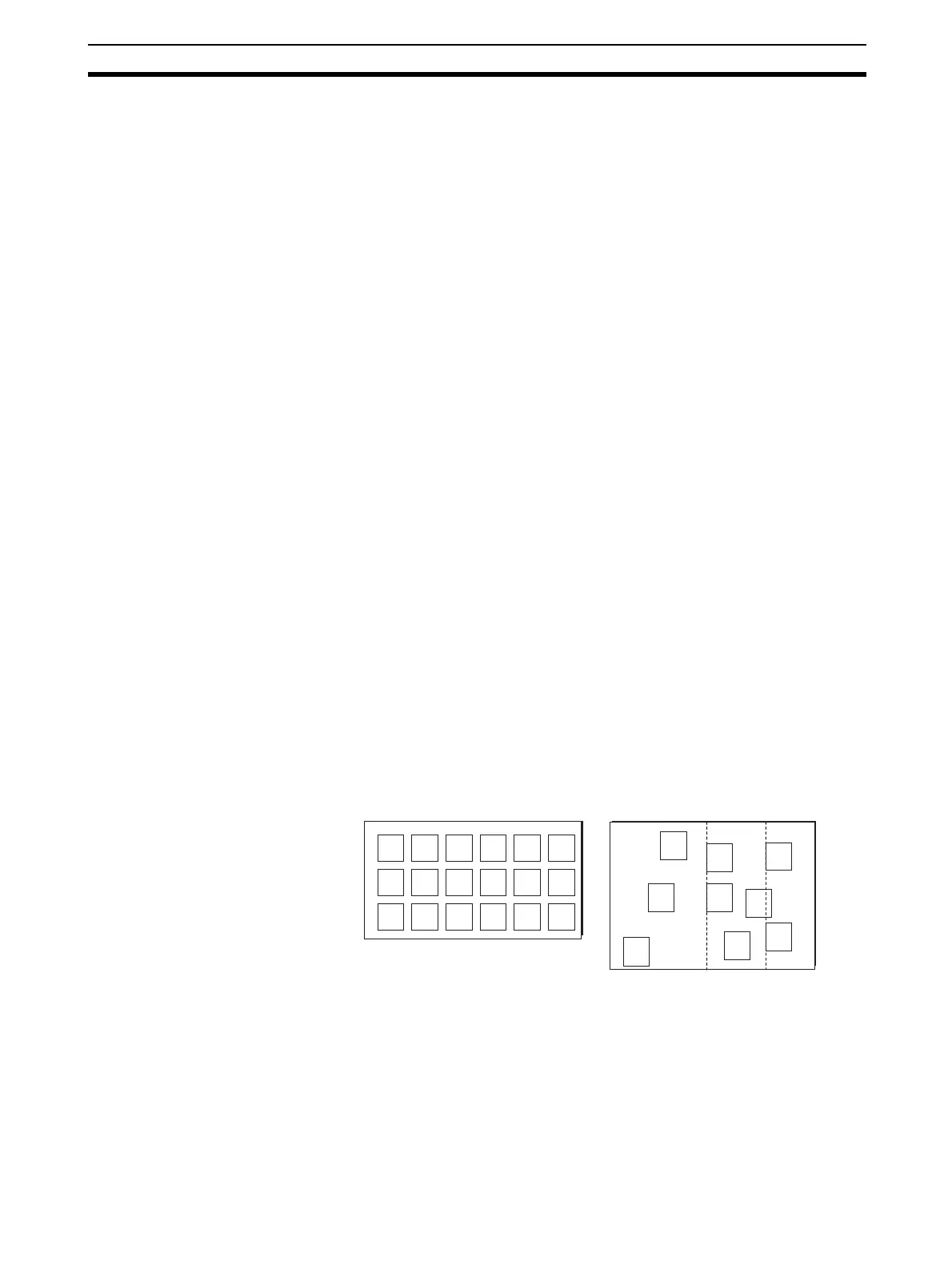
b. To execute according to block diagram position
Select Settings/Setting Block Operating Order from the menus. The
function block diagrams will be executed in order from 1 on, and blocks
within each function block diagram will be executed (for the following
example) 1, 2, 3, etc., through 18.
Note If the same function block is in more than one block diagram, it will
be executed in the block diagram with the smallest number.
• External Controller blocks are executed in order of block address. Only
one External Controller block is executed each cycle.
• Sequence Table and Step Ladder blocks are all executed each cycle in
order of block address.
4. Output User Link Tables (including the Do and Ao field output terminals
created as virtual blocks on the CX-Process Tool)
Block Diagram
A
B
C
D
E
F
G
H
I
J
K
L
M
N
O
P
Q
R
C
B
A
D
E
F
G
H
I
Block Diagram
Fixed Location Mode Free Location Mode