45
Configuration of Instrumentation System Section 1-2
of an instrumentation system is not the same as the operation cycle of the
function blocks; but is a cycle heavily dependent on the CPU Unit's cycle
time.
In most cases, the maximum external analog I/O response cycle is as fol-
lows depending on the operation timing:
“approximately 2 times the CPU Unit's cycle time” + “approximately twice
the operation cycles of the Loop Controller's function blocks”
So, when determining the system configuration, calculate how long the ex-
ternal analog I/O response cycle will be within the instrumentation system
based upon factors such as the CPU Unit's cycle time and the operation
cycles of the Loop Controller's function blocks. Also, assess whether or not
there will be any problems when running applications at the analog I/O re-
sponse cycle that you have calculated.
(For details on the relationship between the Loop Controller's operation cy-
cles and the CPU Unit's cycle time, see 3-2 Description of Operations. For
details on how to calculate the CPU Unit's cycle time, refer to the CS1-se-
ries Operation Manual (Cat. No. W339), 15-4 Computing the Cycle Time.)
7. Evaluation of Using Battery-free Operation for CPU Unit or CPU Unit
Element
Battery-free operation cannot be used for the CS1-H CPU Unit or the CPU
Unit element of a Process-control CPU Unit or Loop-control CPU Unit.
!WARNING Do not use battery-free operation for the CS1-H CPU Unit or the CPU Unit
element of a Process-control CPU Unit or Loop-control CPU Unit. If battery-
free operation is used for the CPU Unit or CPU Unit element, the contents of
the EM Area will not be stable when the power supply is turned ON, possibly
causing illegal values in the HMI data in the Loop Controller.
1-2-3 Description of Basic System Configuration
Mounting of Units for
External Analog I/O
and Contact I/O
The Loop Controller does not have direct external analog I/O and contact I/O
functions. External I/O is achieved via Analog I/O Units and Basic I/O Units
mounted on a basic PLC System (see note). (It is also possible to handle I/O
with external devices through DeviceNet Analog Slaves.)
Note CS Series: CPU Rack, Expansion Rack, Expansion I/O Rack for the C200H,
or SYSMAC BUS Remote I/O Slave Rack
CJ Series: CPU Rack or Expansion Rack
So, in the basic system configuration, Analog I/O Units (Analog Input Unit,
Analog Output Unit, and Analog I/O Unit) must be mounted for the same PLC.
(It is also possible to input and output data for Analog I/O Units on other
nodes in a Controller Link or other network.)
A Basic I/O Unit must also be mounted for the same PLC as necessary.
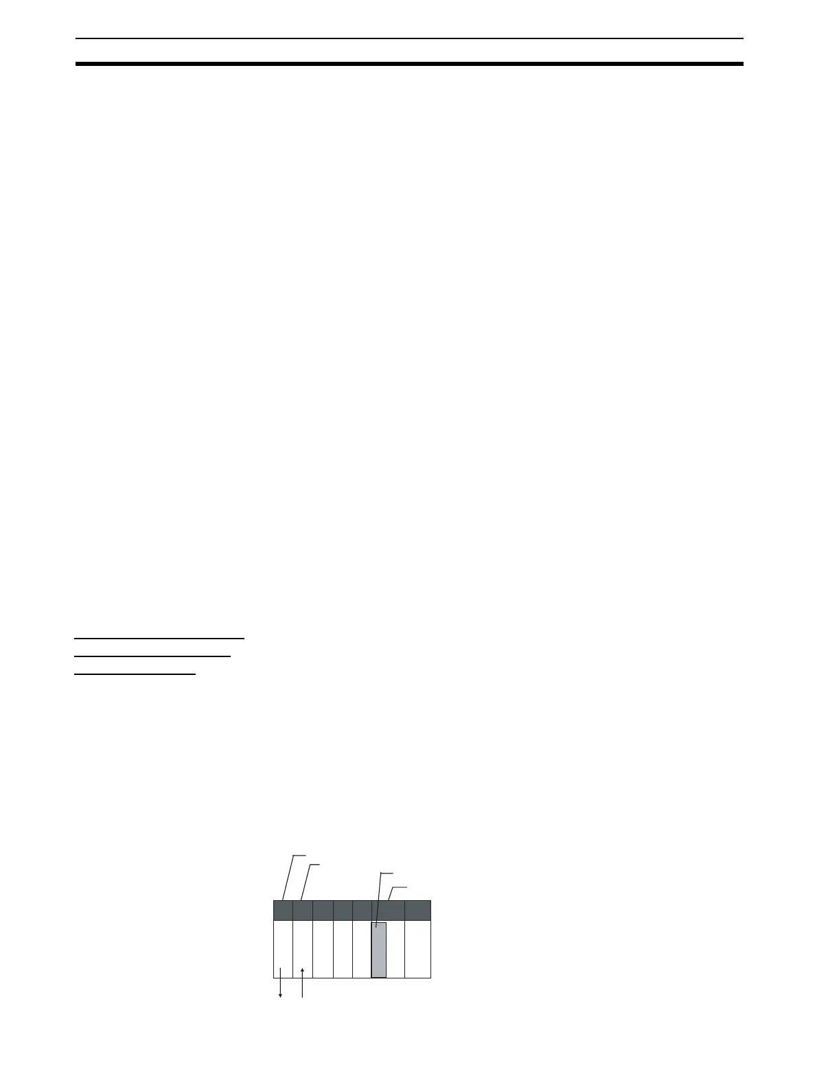
Analog Output Unit
Analog Input Unit
Loop Control Board
CPU Unit