40
Configuration of Instrumentation System Section 1-2
CPU Units
1-2-2 Determining the System Configuration
Check the following points when determining the system configuration:
1,2,3... 1. Number of Analog I/O Points Used on Loop Controller
Which analog signals are input/output on the AI/AO terminals of the Field
Terminal block, and which analog signals are input/output on the CPU Unit
Terminal block or the Expanded CPU Unit Terminal block?
The total number of usable AI/AO terminals on the Field Terminal block
combined with the DO/DI terminals is 80. (For details of the Unit types that
can be used, see 1-2-3 Description of Basic System Configuration.)
The maximum number of usable CPU Unit Terminal blocks is 16. (For de-
tails of I/O memory area that can be specified, see 3-3-3 Exchanging Da-
ta.)
2. Number of Contact I/O Points Used on Loop Controller
Which contact signals are input/output on the DI/DO terminals of the Field
Terminal block, and which contact signals are input/output on the CPU Unit
Terminal block or the Expanded CPU Unit Terminal block?
The total number of DI/DO terminals on the Field Terminal block combined
with the AO/AI terminals is 80 for the LCB01/05, 30 for the CJ1G-
CPU42/43P, and 40 for the CJ1G-CPU44/45P. (For details of the Unit types
that can be used, see 1-2-3 Description of Basic System Configuration.)
The maximum number of usable CPU Unit Terminal blocks is 2,400. (For
details of I/O memory area that can be specified, see 3-3-3 Exchanging
Data.)
3. Current Consumption
Is the current consumption of the Units mounted on the rack less than the
current consumption of the Power Supply Unit?
Refer to CS1-series Operation Manual (Cat. No. W339), 2-6 Unit Current
Consumption.
4. Evaluation of Load Rate
The Loop Controller cyclically processes operation of its own function
blocks asynchronously with I/O refreshing of the CPU Unit. The cycle by
which operations are processed, or the “operation cycle,” is dependent on
the type and number of function blocks used.
For this reason, when many function blocks whose operation takes a long
time to process are used, the actual operation cycle of the entire Loop
Controller or an individual function block increases. As a result, the desired
preset operation cycle sometimes cannot be satisfied.
The ratio between the actual execution time required for processing oper-
ation and the preset operation cycle is called the “load rate.” The maximum
values and current value of each operation cycle group can be confirmed
on CX-Process Tool.
A load rate of 80% or less is required in all operation cycle groups on this
Loop Controller.
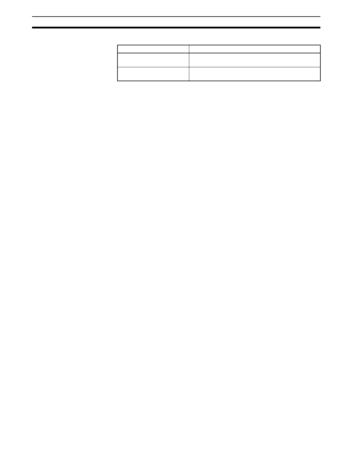
Loop-control CPU Units Description
CJ1G-CPU42P CPU Unit with built-in Loop Control Board. Write lad-
der programs for the CJ1G-CPU42H.
CJ1G-CPU43/44/45P CPU Unit with built-in Loop Control Board. Write lad-
der programs for the CJ1G-CPU43H/44H/45H.