88
Configuration of Function Blocks Section 3-1
All ITEMs excluding the following items can be read and written by FINS com-
mands:
• Sequence commands (ITEM 011 onwards) of Step Ladder Program block
(Block Model 301) and Sequence Table (Block Model 302) rules
Note All analog signals on the Loop Controller are processed (input or output) in %
units. (They are not processed in engineering units.) Though the data range
varies according to each ITEM, the maximum range is −320.00 to +320.00%.
For example, the data range for PV or Set Point in Control blocks such as the
PID block is −15.00 to +115.00%, and the data range for MV is −320.00 to
+320.00%. When analog signals are connected, data is handled with “%” as
the common unit regardless of differences in the data ranges between ITEMs.
(Note, however, that minus values are regarded as 0.00% when entered to
ITEMs whose data range starts from 0.00%.) When the function block’s initial
setting data (S) is downloaded, the internal memory used for calculating the
blocks, and the MV, A/M switch, and R/L switch are initialized. The MV is cal-
culated from 0.
3-1-5 Connecting Function Blocks
• For analog signals (variables) and accumulated value signals, specify the
block address and ITEM number of the source designation in the ITEMs
of the send destination block.
• Specify contacts not in that function block but in the Step Ladder Program
block (Block Model 301) or the Contact Distributor block (Block Model
201).
• Also, specify parameters*1 not in that function block but in the Constant
ITEM Setting block (Block Model 171) or the Variable ITEM Setting block
(Block Model 172).
∗1: Some parameters cannot be set by ITEM Setting blocks. (For details,
refer to the read/write details of each ITEM in the Function Block Refer-
ence Manual.
Note Contacts can be connected only via the Step Ladder Program block (Block
Model 301) or the Contact Distributor block (Block Model 201). In other words,
contacts cannot be connected directly.
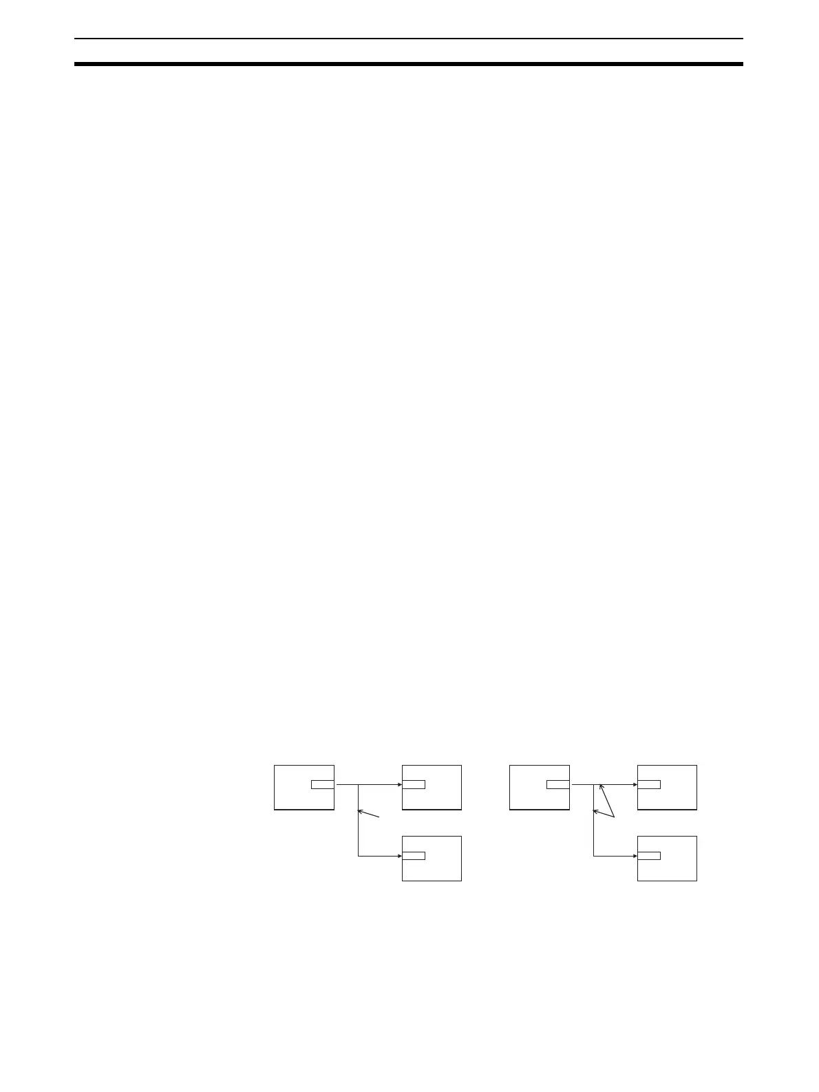
• When connecting accumulated values, analog signals and contact signals
between function blocks, only one signal can be connected to a single
input ITEM. However, an infinite number of branches can be made from a
single output ITEM.
×
×
× ∆
∆
∆
Several branches
possible
∆
∆
∆
×
×
× ∆
∆
∆
Several branches
possible
∆
∆
∆
Contact signal