243
Appendix A
How to Use the Step Ladder Program Block
The Step Ladder Program block (Block Model 301) is used in the following cases:
• When logical operations such as AND, OR and NOT are to be performed on the Loop Controller
• When input of changes in the contact state (OFF to ON or ON to OFF) are to be converted to one-shot
contact outputs that are ON for only one operation cycle
• When system contacts such as constantly ON contacts are to be used on the Loop Controller
• When step progression control, for example, is to be performed on the Loop Controller
Note When contact signals are simply to be connected between function blocks, the Contact Distributor block
(Block Model 201) is used.
To be more precise, the Step Ladder Program block is used in the following applications:
• For setting the conditions for indicating Remote/Local switching
• For setting the conditions for indicating Auto/Manual switching
• For setting the tracking switch conditions
• For setting the MV hold conditions
• For setting the PID switching conditions
• For setting command switch conditions (e.g. tracking switch, run/stop command to ITEM Setting blocks)
• For step progression control of devices
Example
Note 1. The execution cycle of sequence commands in the Step Ladder Program block is slower than the ex-
ecution cycle (cycle time) of commands on the CPU Unit. (0.1 to 2 s cycles follow the operation cycle
of the Step Ladder Program itself.) For this reason, the Step Ladder Program block is used combined
with other function blocks. When high-speed processing is required, use commands on the CPU Unit.
2. At the Step Ladder Program block, external contacts are not directly input and output. They are input
and output via Field Terminal DI or DO terminals.
!WARNING When the OUT instruction from the Step Ladder Program is to be connected to a DO termi-
nal, do not set the address for the OUT instruction from the Step Ladder Program to the
same address as the address for the OUT instruction in the user's program on the CPU Unit.
When writing is performed on identical addresses, the externally connected load may act
unexpectedly and cause injury.
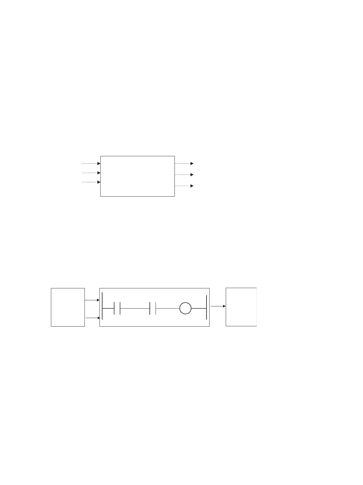
Step Ladder program
(Block Model 301)
One of
•
Logic sequence operation
•
System contact use
•
Step progression control
Contact outpu
Contact input
Advanced PID
(block address)
Advanced PID
(block address
001)
When PID of block address 002 is set to AUTO and the
mode is the remote mode, MV tracking of the PID of block
address 001 is ON.
R/L
A/M
MV
tracking
Step Ladder Program (Block Model 301)
002-086 001-085
A/M MV tracking
002-026
A/M