176
Simple Example of Use Section 4-1
4-1 Simple Example of Use
This section describes the basic procedure for using the Loop Controller for
cascade control.
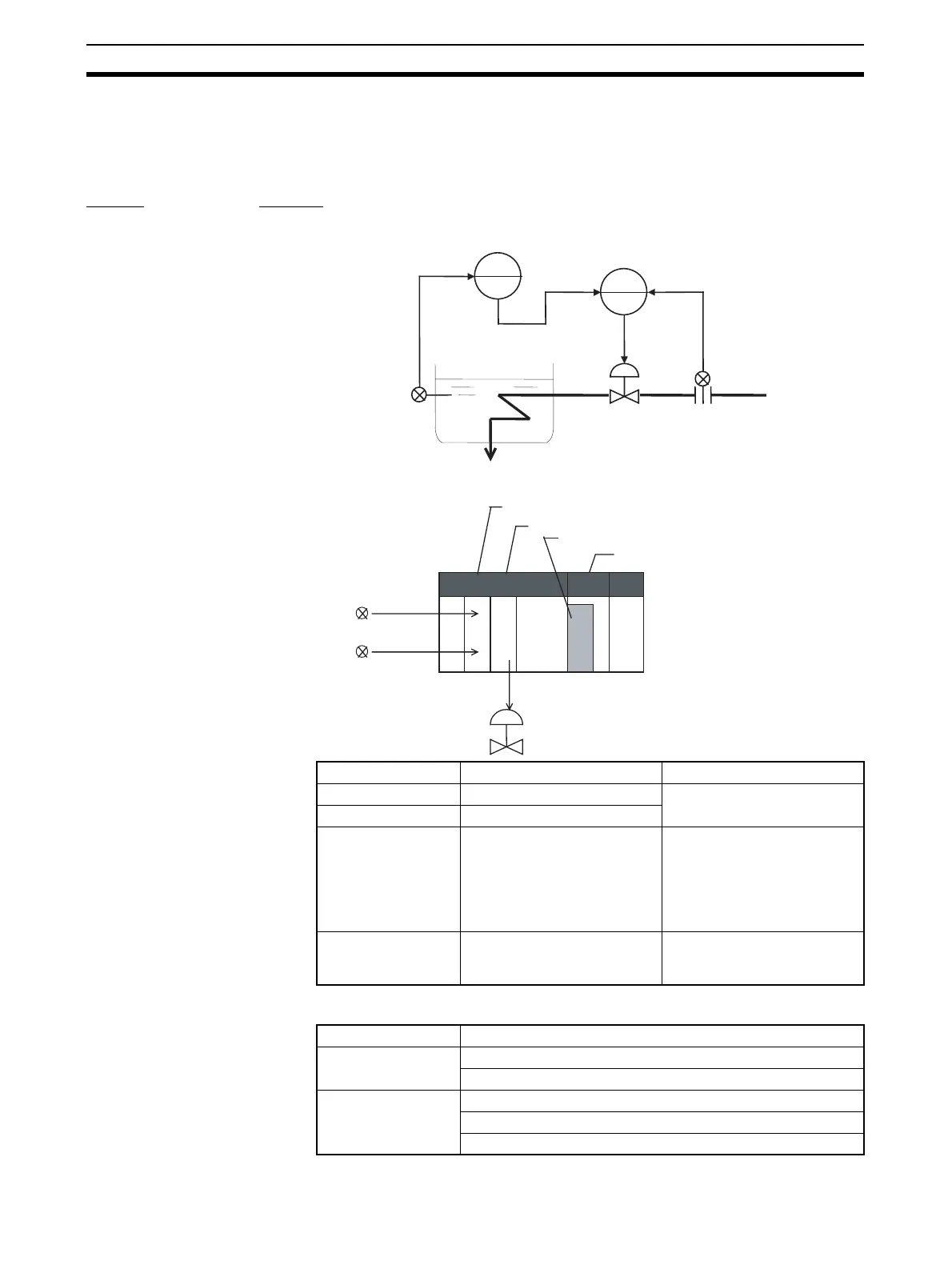
Step 1 Design
1,2,3... 1. Prepare an instrumentation drawing.
2. Decide on the PLC system configuration.
3. Select the required function blocks.
Product name Model Description
CPU Unit CS1H/G-CPU@@
Loop Control Board CS1W-LCB01
Analog Input Unit CS1W-AD041 • Analog input 1:
4 to 20 mA (temperature
conversion input)
• Analog input 2:
4 to 20 mA (differential pres-
sure transmitter input)
Analog Output Unit CS1W-DA041 • Analog output 1:
4 to 20 mA (output to control
valve)
Software type Function block name
Field terminal AI 4-point (Block Model 586)
AO 4-point Terminal (Block Model 587)
Wiring diagram Square Root (Block Model 131)
Basic PID (Block Model 011)
Basic PID (Block Model 011)
PID2
PV 1
MV 1
PID1
MV 2
PV 2
0.0 to 400.0 m
3
/HR
0.0 to 300.0
°
C
CPU Unit
Loop Control Board
Analog Output Unit
Temperature
converter
4 to 20 mA
Differential pressure
transmitter
4 to 20 mA
4 to 20 mA
Control valve
Analog Input Unit